Difference between revisions of "Process Integration"
m (Text replacement - "'''SEBoK v. 2.2, released 15 May 2020'''" to "'''SEBoK v. 2.3, released 30 October 2020'''") |
m (Text replacement - "<center>'''SEBoK v. 2.3, released 30 October 2020'''</center>" to "<center>'''SEBoK v. 2.4, released 19 May 2021'''</center>") |
||
| Line 109: | Line 109: | ||
<center>[[System Life Cycle Process Models: Iterative|< Previous Article]] | [[Life Cycle Models|Parent Article]] | [[Lean Engineering|Next Article >]]</center> | <center>[[System Life Cycle Process Models: Iterative|< Previous Article]] | [[Life Cycle Models|Parent Article]] | [[Lean Engineering|Next Article >]]</center> | ||
| − | <center>'''SEBoK v. 2. | + | <center>'''SEBoK v. 2.4, released 19 May 2021'''</center> |
[[Category:Part 3]][[Category:Topic]] | [[Category:Part 3]][[Category:Topic]] | ||
[[Category:Life Cycle Models]] | [[Category:Life Cycle Models]] | ||
Revision as of 05:16, 18 May 2021
Lead Authors: Kevin Forsberg, Bud Lawson
When performing systems engineering activities, it is important to consider the mutual relationship between processes and the desired system. The type of system (see Types of Systems) being produced will affect the needed processes, as indicated in system life cycle process drivers and choices. This may cause the tailoring of defined processes as described in application of systems engineering standards.
Process and Product Models
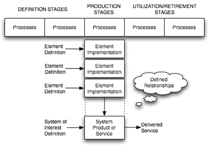
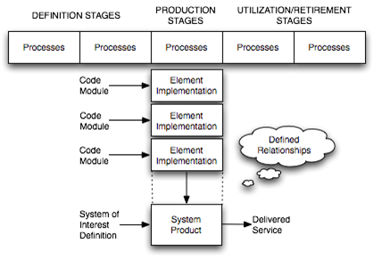
Figure 1 of life cycle models introduced the perspective of viewing stage work products provided by process execution as versions of a system-of-interest (SoI) at various life stages. The fundamental changes that take place during the life cycle of any man-made system include definition, production, and utilization. When building upon these, it is useful to consider the structure of a generic process and product life cycle stage model as portrayed in Figure 1 below.
The (T) model indicates that a definition stage precedes a production stage where the implementation (acquisition, provisioning, or development) of two or more system elements has been accomplished. The system elements are integrated according to defined relationships into the SoI. Thus, both the process and product aspects are portrayed. The implementation and integration processes are followed in providing the primary stage results—namely, in assembled system product or service instances. However, as noted in life cycle models, the definition of the SoI when provided in a development stage can also be the result of first versions of the system. For example, a prototype, which may be viewed as a form of production or pre-production stage. Following the production stage is a utilization stage. Further relevant stages can include support and retirement. Note that this model also displays the important distinction between definition versus implementation and integration.
According to ISO/IEC/IEEE 15288 (2015), this structure is generic for any type of man-made SoI to undergo life cycle management. The production stage thus becomes the focal point of the (T) model at which system elements are implemented and integrated into system product or service instances based upon the definitions. For defined physical systems, this is the point at which product instances are manufactured and assembled (singularly or mass-produced). For non-physical systems, the implementation and integration processes are used in service preparation (establishment) prior to being instantiated to provide a service. For software systems, this is the point at which builds that combine software elements into versions, releases, or some other form of managed software product are produced.
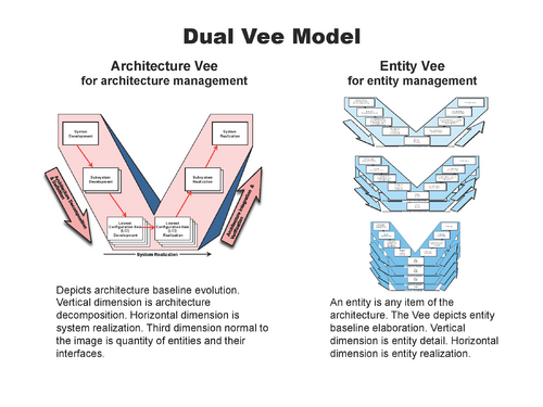
Using recursive decomposition, the implementation of each system element can involve the invocation of the standard again at the next lowest level, thus treating the system element as a SoI in its own right. A new life cycle structure is then utilized for the lower level SoIs.
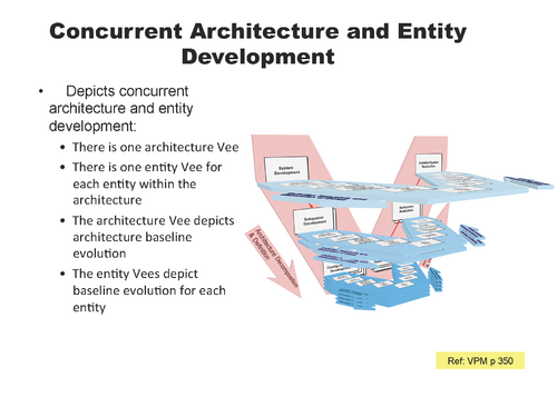
This is illustrated in the Dual Vee model (Figures 2a and 2b). The Dual Vee model is a three-dimensional system development model that integrates product and process in the creation of the system and component architectures. It emphasizes
- concurrent opportunity and risk management;
- user in-process validation;
- integration, verification, and validation planning; and
- verification problem resolution.
When decomposition terminates according to the practical need and risk-benefit analysis, system elements are then implemented (acquired, provisioned, or developed) according to the type of element involved.
A practical aspect that can impact the process and product aspect is the decision to use off-the-shelf elements in commercial-off-the-shelf (COTS) form. In this case, further decomposition of the element is not necessary. The use of COTS elements (and their internally created neighbor or non-development item (NDI)) has become widespread, and they have proven their value. However, developers must make sure that the COTS product is appropriate for their environment.
A known flaw which occurs infrequently in normal use of the product in its intended environment may be benign and easily dealt with. In a new situation, it could have dramatic adverse consequences, such as those that occurred on the USS Yorktown Cruiser in 1998 (Wired News Contributors 1998). The customer mandated that Windows NT be used as the primary operating system for the ship. A divide by zero fault caused the operating system to fail, and the ship was dead in the water. It had to be towed back to port on three occasions.
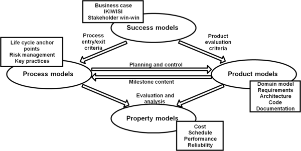
Spiral models concurrently engineer not only process and product models, but also property and success models. Figure 3 shows how these models provide checks and balances, both at milestone reviews and as individual model choices are made. Methods and tools supporting this concurrent engineering are provided in “When Models Collide: Lessons from Software System Analysis” (Boehm and Port 1999), “Avoiding the Software Model-Clash Spiderweb” (Boehm, Port, and Al-Said 2000), and “Detecting Model Clashes During Software Systems Development” (Al-Said 2003).
For software systems, entry into the production stages is the point at which builds that combine software elements (code modules) into versions, releases, or some other form of managed software product are created. Thus, the major difference between systems in general and software systems is the slight variant of the generic model as presented in Figure 4.
Stage Execution Order
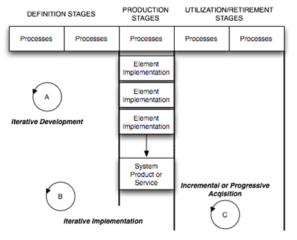
A sequential execution of life cycle stages is the most straightforward. As presented in System Life Cycle Process Models: Vee and System Life Cycle Process Models: Iterative, variants of the Vee model and the spiral model provide non-sequential models when practical considerations require a non-linear execution of life cycle stages. Building upon these two models, it is important to note that various types of complex systems require that the stages of the life cycle model be revisited as insight (knowledge) is gained, as well as when stakeholder requirements change. The iterations may involve necessary changes in the processes and in the product or service system. Thus, within the context of the (T) stage model, various orderings of stage execution - reflecting forms of non-sequential stage ordering - can be conveniently described, as portrayed in Figure 5.
Each pattern of stage execution involves iteration of the previous stages, perhaps with altered requirements for the processes or the system. The heavy lines in Figure 5 denote the demarcation of the revisited end points. Three are iterative forms, for which several variants can be extracted:
- Iterative development is quite frequently deployed in order to assess stakeholder requirements, analyze the requirements, and develop a viable architectural design. Thus, it is typical that the concept stage may be revisited during the development stage. For systems where products are based upon physical structures (electronics, mechanics, chemicals, and so on), iteration after production has begun can involve significant costs and schedule delays. It is, therefore, important to get it "right" before going to production. The early stages are thus used to build confidence (verify and validate) that the solution works properly and will meet the needs of the stakeholders. Naturally, such an approach could be used for software and human activity systems as well; however, due to their soft nature, it can be useful to go further by experimenting and evaluating various configurations of the system.
- Iterative development and implementation involves producing (defining, implementing, and integrating) various versions of the system, evaluating how well they meet stakeholder requirements, perhaps in the context of changing requirements, and then revisiting the concept and/or development stages. Such iterations are typical within software system development, where the cost of production is not as significant as for defined physical systems. A variant of this approach is the spiral model, where successive iterations fill in more detail (Boehm and May 1998). The use of this approach requires careful attention to issues related to baseline and configuration management. In this approach, significant verification (testing) should be performed on software systems in order to build confidence that the system delivered will meet stakeholder requirements.
- Incremental or progressive acquisition involves releasing systems in the form of products and/or services to the consumers. This approach is appropriate when structural and capability (functions) changes are anticipated in a controlled manner after deployment. The use of this approach can be due to not knowing all of the requirements at the beginning, which leads to progressive acquisition/deployment, or due to a decision to handle the complexity of the system and its utilization in increments—namely, incremental acquisition. These approaches are vital for complex systems in which software is a significant system element. Each increment involves revisiting the definition and production stages. The utilization of these approaches must be based upon well-defined, agreed relationships between the supplying and acquiring enterprises. In fact, the iteration associated with each resulting product and/or service instance may well be viewed as a joint project, with actor roles being provided by both enterprises.
In all of the approaches it is wise to use modeling and simulation techniques and related tools to assist in understanding the effect of changes made in the complex systems being life cycle managed. These techniques are typically deployed in the earlier stages; however, they can be used in gaining insight into the potential problems and opportunities associated with the latter stages of utilization and maintenance (for example, in understanding the required logistics and help-desk aspects).
Allocating and Meeting Requirements - Integration of Process and Product Models
Regardless of the order in which life cycle stages are executed, stakeholder requirements for the system, including changed requirements in each iteration, must be allocated into appropriate activities of the processes used in projects for various stages as well as to the properties of the elements of the product system or service system and their defined relationships. This distribution was illustrated in the fourth variant of Lawson’s T-model as presented in System Life Cycle Process Models: Iterative and System Life Cycle Process Models: Vee.
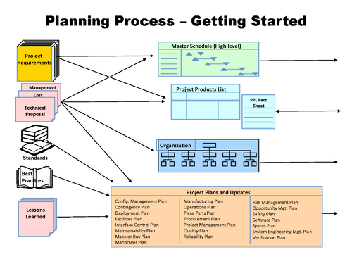
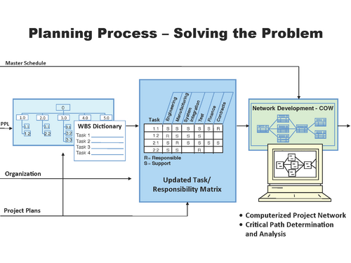
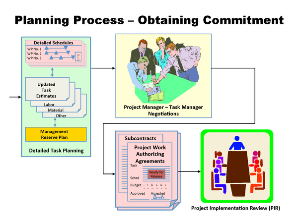
Ideally, the project management team should implement proven processes that will integrate the technical process models with the project management product models to manage any of the processes discussed earlier, including incremental and evolutionary development. The processes shown are the project management flow, starting with the beginning of the development phase (Forsberg, Mooz, and Cotterman 2005, 201).
References
Works Cited
Boehm, B. and W. May. 1988. "A Spiral Model of Software Development and Enhancement." IEEE Computer 21(5): 61-72.
Boehm, B. and D. Port. 1999. "When Models Collide: Lessons From Software System Analysis." IT Professional 1(1): 49-56.
Boehm, B., J. Lane, S. Koolmanojwong, and R. Turner (forthcoming). Embracing the Spiral Model: Creating Successful Systems with the Incremental Commitment Spiral Model. New York, NY, USA: Addison Wesley.
Forsberg, K., H. Mooz, and H. Cotterman. 2005. Visualizing Project Management. 3rd ed. New York, NY, USA: J. Wiley & Sons.
ISO/IEC/IEEE. 2015.Systems and Software Engineering-- System Life Cycle Processes. Geneva, Switzerland: International Organisation for Standardisation / International Electrotechnical Commissions.ISO/IEC/IEEE 15288:2015
Lawson, H. 2010. A Journey Through the Systems Landscape. London, UK: College Publications.
Wired News Contributors. 2011. “Sunk by Windows NT,” Wired News, last modified July 24, 1998. Accessed on September 11, 2011. Available at http://www.wired.com/science/discoveries/news/1998/07/13987.
Primary References
Boehm, B. and W. May. 1988. “A Spiral Model of Software Development and Enhancement.” IEEE Computer. 21(5): 61-72.
Forsberg, K., H. Mooz, and H. Cotterman. 2005. Visualizing Project Management, 3rd ed. New York, NY, USA: John Wiley & Sons.
Lawson, H. 2010. A Journey Through the Systems Landscape. London, UK: College Publications.
Additional References
Al-Said, M. 2003. "Detecting Model Clashes During Software Systems Development." PhD Diss. Department of Computer Science, University of Southern California, December 2003.
Boehm, B., J. Lane, S. Koolmanojwong, and R. Turner. (forthcoming). Embracing the Spiral Model: Creating Successful Systems with the Incremental Commitment Spiral Model. New York, NY, USA: Addison Wesley.
Boehm, B. and D. Port. 1999. "Escaping the Software Tar Pit: Model Clashes and How to Avoid Them." ACM Software Engineering Notes. (January, 1999): p. 36-48.
Boehm, B. and D. Port. 1999. "When Models Collide: Lessons From Software System Analysis." IT Professional. 1(1): 49-56.
Boehm, B., D. Port, and M. Al-Said. 2000. "Avoiding the Software Model-Clash Spiderweb." IEEE Computer. 33(11): 120-122.
Lawson, H. and M. Persson. 2010. “Portraying Aspects of System Life Cycle Models.” Proceedings of the European Systems Engineering Conference (EuSEC). 23-26 May 2010. Stockholm, Sweden.
