|
|
| Line 1: |
Line 1: |
| − | Logical Architecture Dodel evelopment may be used as a task of the activity "Develop candidate architectures models and views", or a sub-process of the System Architecture Definition process (see '''[[System Architecture]]''' article). Its purpose is to elaborate models and views of the functionality and behavior of the future [[System (glossary)|system]] as it should operate, while in service. The [[Logical Architecture (glossary)|logical architecture]] modelof a system is composed of a set of related technical concepts and principles that support the logical operation of the system. It may include a [[Functional Architecture (glossary) |functional architecture]] view, a [[Behavioral Architecture (glossary)|behavioral architecture]] view, and a [[Temporal Architecture (glossary)|temporal architecture]] view. Other additional views are suggested in architectural frameworks, depending on the domain; refer to the Department of Defense (DoD) ''Architecture Framework'' (DoDAF) (DoD 2010), ''The Open Group Architectural Framework'' (TOGAF) (The Open Group 2011), etc).
| + | ---- |
| | + | '''''Lead Author:''''' ''Rick Adcock'', '''''Contributing Authors:''''' ''Janet Singer, Duane Hybertson'' |
| | + | ---- |
| | + | This knowledge area (KA) provides a guide for applying the {{Term|Systems Approach (glossary)|systems approach}} as a means of identifying and understanding complex problems and opportunities, synthesizing possible alternatives, analyzing and selecting the best alternative, implementing and approving a solution, as well as deploying, using and sustaining {{Term|Engineered System (glossary)|engineered system}} solutions. The active participation of stakeholders during all the activities of the systems approach is the key to the success of the systems approach. |
| | | | |
| − | Note: The term ''Logical Architecture'' is a contraction of the expression ''Logical View of the System Architecture''.
| + | In an engineered system context, a systems approach is a holistic approach that spans the entire life of the system; however, it is usually applied in the development and operational/support life cycle stages. This knowledge area defines a systems approach using a common language and intellectual foundation to ensure that practical systems concepts, principles, patterns and tools are accessible to perform {{Term|Systems Engineering (glossary)|systems engineering}} (SE), as is discussed in the introduction to [[Foundations of Systems Engineering|Part 2: Foundations of Systems Engineering]]. |
| | | | |
| − | ==Concepts and Principles== | + | ==Topics== |
| | + | Each part of the Guide to the SE Body of Knowledge (SEBoK) is divided into KAs, which are groupings of information with a related theme. The Kas, in turn, are divided into topics. This KA contains the following topics: |
| | + | *[[Overview of the Systems Approach]] |
| | + | *[[Engineered System Context]] |
| | + | *[[Identifying and Understanding Problems and Opportunities]] |
| | + | *[[Synthesizing Possible Solutions]] |
| | + | *[[Analysis and Selection between Alternative Solutions]] |
| | + | *[[Implementing and Proving a Solution]] |
| | + | *[[Deploying, Using, and Sustaining Systems to Solve Problems]] |
| | + | *[[Applying the Systems Approach]] |
| | | | |
| − | ===Functional Architecture Model=== | + | ==Systems Approach== |
| | + | This KA describes a high-level framework of activities and principles synthesized from the elements of the systems approach, as described earlier in Part 2 of the SEBoK, and is mapped to the articles [[Concepts of Systems Thinking]], [[Principles of Systems Thinking]], and [[Patterns of Systems Thinking]]. The concept map in Figure 1 describes how the knowledge is arranged in this KA and the linkage to the KA in Part 3. |
| | | | |
| − | A [[Functional Architecture (glossary) |functional architecture]] model is a set of functions and their sub-functions that defines the transformations performed by the system to complete its mission.
| + | [[File:Fig_1_Systems_Engineering_and_the_Systems_Approach_RA.png|thumb|650px|center|'''Figure 1. Systems Engineering and the Systems Approach.''' (SEBoK Original)]] |
| | | | |
| − | '''Function and Input-Output Flow''' - In the context of System Architecture, functions and input-output flows are architecture entities. A [[Function (glossary) |function]] is an action that transforms inputs and generates outputs, involving data, materials, and/or energies. These inputs and outputs are the flow items exchanged between functions. The general mathematical notation of a function is '''''y''''' ''= ƒ('' '''''x''''' '',t)'', in which '''y''' and '''x''' are vectors that may be represented graphically and t = time.
| + | According to Jackson et al. (2010, 41-43), the systems approach to engineered systems is a problem-solving paradigm. It is a comprehensive problem identification and resolution approach based upon the principles, concepts, and tools of {{Term|Systems Thinking (glossary)|systems thinking}} and {{Term|Systems Science (glossary)|systems science}}, along with the concepts inherent in engineering problem-solving. It incorporates a holistic systems view that covers the larger context of the system, including engineering and operational environments, stakeholders, and the entire life cycle. |
| | + | |
| | | | |
| − | In order to define the complete set of functions of the system, one must identify all the functions necessitated by the system and its derived requirements, as well as the corresponding inputs and outputs of those functions. Generally speaking, there are two kinds of functions:
| + | Successful systems practice should not only apply systems thinking to the system being created but should also utilize systems thinking in consideration of the way in which work is planned and conducted. See [[Enabling Systems Engineering|Part 5: Enabling Systems Engineering]] for further discussions on how individuals, teams, businesses and enterprises may be enabled to perform systems engineering. |
| − | | |
| − | # Functions that are directly deduced from functional and interface requirements. These functions express the expected services of a system necessary to meet its [[System Requirement (glossary)|system requirements]].
| |
| − | # Functions that are derived and issued from the alternative solutions of [[Physical Architecture (glossary)|physical architecture]] model and are dependent upon the result of the design; additionally, they rely upon on technology choice to implement the logical architecture model elements.
| |
| − | | |
| − | '''Functional Hierarchy/Decomposition of Functions''' - At the highest level of a hierarchy (Figure 1), it is possible to represent a system as a unique, central function (defined as the system's mission) that in many ways is similar to a "black box" ("F0" in plan A-0 in Figure 1). In order to understand, in detail, what the system does, this "head-of-hierarchy" (F0) is broken down into sub-functions (F1, F2, F3, F4) grouped to form a sub-level of the hierarchy (plan A0), and so on. Functions of the last level of a functional hierarchy can be called leaf-functions (F21, F22, F23, F24 in plan A2). Hierarchies (or breakdowns) decompose a complex or global function into a set of functions for which physical solutions are known, feasible, or possible to imagine. However, a static functional hierarchy does not represent how effectively the flows of inputs and outputs are exchanged.
| |
| − | | |
| − | [[File:Decomposition_of_Functions_AF_071112(2).png|600px|thumb|center|'''Figure 1. Decomposition of Functions (Faisandier 2012).''' Permission granted by Sinergy'Com. All other rights are reserved by the copyright owner.]]
| |
| − | | |
| − | ===Behavioral Architecture Model===
| |
| − | | |
| − | A [[Behavioral Architecture (glossary) |behavioral architecture]] model is an arrangement of functions and their sub-functions as well as interfaces (inputs and outputs) that defines the execution sequencing, conditions for control or data-flow, and performance level necessary to satisfy the system requirements (ISO/IEC 26702 2007). A behavioral architecture model can be described as a set of inter-related scenarios of functions and/or [[Operational Mode (glossary) |operational modes]].
| |
| − | | |
| − | '''Control (Trigger)''' - A control flow is an element that activates a function as a condition of its execution. The state of this element, or the condition it represents, activates or deactivates the function (or elements thereof). A control flow can be a signal or an event, such as a switch being moved to the ''on'' position, an alarm, a trigger, a temperature variation, or the push of a key on a keyboard.
| |
| − | | |
| − | '''Scenario (of Functions)''' - A scenario of functions is a chain of functions that are performed as a sequence and synchronized by a set of control flows to work to achieve a global transformation of inputs into outputs, as seen in the figures below. A scenario of functions expresses the dynamic of an upper level function. A behavioral architecture is developed by considering both scenarios for each level of the functional hierarchy and for each level of the system hierarchy. When representing scenarios of functions and behavioral architecture models, it is appropriate to use diagrams as modeling techniques, such as functional flow block diagrams (FFBD) (Oliver, Kelliher, and Keegan 1997) or activity diagrams, developed with SysML (OMG 2010). Figures 2 and 3 provide examples of these diagrams.
| |
| − | | |
| − | [[File:Illustration_of_a_scenario_(eFFBD)_AF_071112.png|thumb|900px|center|'''Figure 2. Illustration of a Scenario (eFFBD).''' (SEBoK Original)]]
| |
| − | | |
| − | [[File:Illustration_of_a_scenario_Activity_Diagram_AF_071112.png|thumb|900px|center|'''Figure 3. Illustration of a Scenario (Activity Diagram).''' (SEBoK Original)]]
| |
| − | | |
| − | '''Operational Mode''' - A scenario of functions can be viewed by abstracting the transformation of inputs into outputs of each function and focusing on the active or non-active state of the function and its controls. This view is called a ''scenario of modes'', which is a chain of modes performed as a sequence of transitions between the various modes of the system. The transition from one mode to another is triggered by the arrival of a control flow (event/trigger). An action (function) can be generated within a transition between two modes following the arrival of an event or a trigger, as demonstrated in Figure 4 below.
| |
| − | | |
| − | [[File:SEBoKv075_KA-SystDef_Scenario_of_Operational_Modes.png|300px|thumb|center|'''Figure 4. Scenario of Operational Modes (Faisandier 2012).''' Permission granted by Sinergy'Com. All other rights are reserved by the copyright owner.]]
| |
| − | | |
| − | '''Behavioral Patterns''' - When defining scenarios or behavioral architecture models, architects may opt to recognize and use known models to represent the expected transformations and behaviors. Patterns are generic basic models that may be more or less sophisticated depending on the complexity of the treatment. (Gamma, Helm, Johnson, and Vlissides 1995) A pattern can be represented with different notations. Behavioral patterns are classified into several categories, which can be seen in the following examples:
| |
| − | * Basic patterns or constructs linking functions - such as sequence, iteration, selection, concurrence, multiple exits, loops with an exit, and replication.
| |
| − | * Complex patterns - such as monitoring a treatment, exchanging a message, man machine interfaces, modes monitoring, real-time monitoring of processes, queue management, and continuous monitoring with supervision.
| |
| − | * Failure detection, identification, and recovery (FDIR) patterns - such as passive redundancies, active redundancies, semi-active redundancies, and treatments with reduced performance.
| |
| − | | |
| − | ===Temporal Architecture Model===
| |
| − |
| |
| − | A [[Temporal Architecture (glossary) |temporal architecture]] model is a classification of the functions of a system that is derived according to the frequency level of execution. Temporal architecture models include the definition of synchronous and asynchronous aspects of functions. The decision monitoring that occurs inside a system follows the same temporal classification because the decisions are related to the monitoring of functions.
| |
| − | | |
| − | '''Temporal and Decisional Hierarchy Concept''' - Not every function of a system is performed at the same frequency. The frequencies change depending on the time and the manner in which the functions are started and executed. One must therefore consider several classes of performance. There are synchronous functions that are executed cyclically and asynchronous functions that are executed following the occurrence of an event or trigger.
| |
| − | | |
| − | To be more specific, ''real-time'' systems and ''command-control'' systems combine cyclical operations (synchronous) and factual aspects (asynchronous). Cyclical operations consist of sharing the execution of functions according to frequencies, which depend on either the constraints of capture or dispatching the input/output and control flows. Two types of asynchronous events can be distinguished:
| |
| − | | |
| − | # Disturbances on High Frequencies (bottom of figure 5) - Decisions that are made at either the level they occur or one level above. The goal is to deter disturbances from affecting the low frequencies so that the system continues to achieve its mission objectives. This is the way to introduce exception operations, with the typical example relating to operations concerns, breakdowns, or [[Failure (glossary)|failures]].
| |
| − | # Changes on Low Frequencies (top of figure 5) - Decisions pertaining to changes that are made at the upper levels. The ultimate goal is to transmit them toward bottom levels to implement the modifications. A typical example relates to operator actions, maintenance operations, etc.
| |
| − | | |
| − | [[File:SEBoKv05 KA-SystDef Temporal and decision hierarchy levels.png|450px|thumb|center|'''Figure 5. Temporal and Decision Hierarchy Levels (Faisandier 2012).''' Permission granted by Sinergy'Com. All other rights are reserved by the copyright owner.]]
| |
| − | | |
| − | ==Process Approach==
| |
| − | | |
| − | ===Purpose===
| |
| − | The purpose of the Logical Architecture Model Development is to define, select, and synthesize a system’s logical architecture model to provide a framework against which to verify that a future system will satisfy its system requirements in all operational scenarios, within which trade-offs between system requirements can be explored in developing such systems.
| |
| − | | |
| − | Generic inputs to the process include system requirements, generic architecture patterns that architects identify and use to answer requirements, outcomes from system analysis processes, and feedback from system verification and validation processes. Depending on the Life Cycle Model that is chosen, there will be iterations through which these inputs and outputs, and the relationships between them evolve and change throughout the process.
| |
| − | | |
| − | Generic outputs from the process are either a single logical architecture model or a set of candidate logical architecture models together with the selected independent logical architecture model and a rationale for its selection. They include, at minimum, views and models. These involve functional, behavioral and temporal views; a traceability matrix between logical architecture model elements and system requirements.
| |
| − | | |
| − | ===Activities of the Process===
| |
| − | Major activities and tasks performed during this process include the following:
| |
| − | | |
| − | * Identify and analyze functional and behavioral elements:
| |
| − | ** Identify functions, [[Input-Output Flow (glossary) |input-output flows]], [[Operational Mode (glossary)|operational modes]], [[Transition of Modes (glossary)|transition of modes]], and [[Operational Scenario (glossary)|operational scenarios]] from system requirements by analyzing the functional, interface, and operational requirements.
| |
| − | ** Define necessary inputs and controls (energy, material, and data flows) to each function and outputs that result in the deduction of the necessary functions to use, transform, move, and generate the input-output flows.
| |
| − | * Assign system requirements to functional and behavioral elements:
| |
| − | ** Formally characterize functions expressions and their attributes through the assignment of performance, effectiveness, and constraints requirements. In particular, study the temporal aspects from requirements to assign duration, response time, and frequency to functions.
| |
| − | ** Formally characterize the input, output, and control flows expressions and their attributes through assignment of interface, effectiveness, operational, temporal and constraints requirements.
| |
| − | ** Establish traceability between system requirements and these functional and behavioral elements.
| |
| − | * Define candidate logical architecture models For each candidate:
| |
| − | ** Analyze operational modes as stated in the system requirements (if any) and/or use previously defined elements to model sequences of operational modes and the transition of modes. Eventually decompose the modes into sub-modes and then establish for each operational mode one or several scenarios of functions recognizing and/or using relevant generic behavioral patterns.
| |
| − | ** Integrate these scenarios of functions in order to get a behavioral architecture model of the system (a complete picture of the dynamic behavior).
| |
| − | ** Decompose previously defined logical elements as necessary to look towards implementation.
| |
| − | ** Assign and incorporate temporal constraints to previously defined logical elements, such as the period of time, duration, frequency, response-time, timeout, stop conditions, etc.
| |
| − | ** Define several levels of execution frequency for functions that correspond to levels of decision, in order to monitor system operations, prioritize processing on this time basis, and share out functions among those execution frequency levels to get a temporal architecture model.
| |
| − | ** Perform functional failure modes and effects analysis and update the logical architecture elements as necessary.
| |
| − | ** Execute the models with simulators (when possible) and tune these models to obtain the expected characteristics.
| |
| − | * Synthesize the selected independent logical architecture model:
| |
| − | ** Select the logical architecture by assessing the candidate logical architecture models against assessment criteria (related to system requirements) and compare them, using the system analysis process to perform assessments and decision management process for the selection (see the [[System Analysis]] and [[Decision Management]] topics). This selected logical architecture model is called ''independent logical architecture model'' because, as much as possible, it is independent of implementation decisions.
| |
| − | ** Identify and define derived logical architecture model elements created for the necessity of design and corresponding with the derived system requirements. Assign these requirements to the appropriate system (current studied system or external systems).
| |
| − | ** Verify and validate the selected logical architecture models (using as executable models as possible), make corrections as necessary, and establish traceability between system requirements and logical architecture model elements.
| |
| − | * Feedback logical architecture model development and system requirements. This activity is performed after the physical architecture model development process:
| |
| − | ** Model the ''allocated logical architecture'' to systems and system elements, if such a representation is possible, and add any functional, behavioral, and temporal elements as needed to synchronize functions and treatments.
| |
| − | ** Define or consolidate derived logical and physical elements induced by the selected logical and physical architecture models. Define the corresponding derived requirements and allocate them to appropriate logical and physical architectures elements. Incorporate these derived requirements into the requirements baselines of impacted systems.
| |
| − | | |
| − | ===Artifacts, Methods and Modeling Techniques===
| |
| − | Logical architecture descriptions use modeling techniques that are grouped under the following types of models. Several methods have been developed to support these types of models (some are executable models):
| |
| − | | |
| − | * Functional Models – These include models such as the structured analysis design technique (SADT/IDEF0), system analysis & real time (SA-RT), enhanced Functional Flow Block Diagrams (eFFBD), and the function analysis system technique (FAST).
| |
| − | * Semantic Models- These include models such as entities-relationships diagrams, class diagrams, and data flow diagrams.
| |
| − | * Dynamic Models – These include such models as state-transition diagrams, state-charts, eFFBDs, state machine diagrams (SysML), activity diagrams (SysML) (OMG. 2010), and petri nets.
| |
| − | | |
| − | Depending on the type of domain (e.g. defense, enterprise), architecture frameworks such as DoDAF (DoD 2010), TOGAF (The Open Group 2011), the Zachman framework (Zachman 2008), etc. provide descriptions that can help to represent additional aspects/views of architectures - see the section 'Enterprise Architecture Frameworks & Methodologies' in [[Enterprise Systems Engineering Key Concepts]]. See also practical means for using general templates related to ISO/IEC/IEEE 42010 (2011), which are available at: [http://www.iso-architecture.org/42010/templates].
| |
| − | | |
| − | ==Practical Considerations==
| |
| − | As stated above, the purpose of the logical architecture model is to provide a description of what a system must be able to do to satisfy the stated need. This should help to ensure that the needs and/or concerns of all stakeholders are addressed by any solution, and that innovative solutions, as well as those based on current solution technologies, can be considered. In practice it is human nature for problem stakeholders to push their own agendas and for solution architects or designers to offer their familiar solutions. If a logical architecture model is not properly enforced with the chosen life cycle, it is easy for both problem and solution stakeholders to ignore it and revert to their own biases (see Part 5 [[Enabling Systems Engineering]]). This is exacerbated if the logical architecture model becomes an end in its own right or disconnected from the main lifecycle activities. This can occur either through the use of abstract language or notations, levels of detail, time taken, or an overly complex final architecture that does not match the purpose for which it was created. If the language, scope, and timeliness of the architecture are not matched to the problem stakeholder or solution providers, it is easier for them to overlook it. Key pitfalls and good practices which can help to avoid problems related to logical architecture model are described in the next two sections.
| |
| − | | |
| − | ===Pitfalls===
| |
| − | Some of the key pitfalls encountered in developing logical architecture are provided in Table 1.
| |
| − | | |
| − | <center>
| |
| − | {|
| |
| − | |+'''Table 1. Pitfalls with Logical Architecture Development.''' (SEBoK Original)
| |
| − | !Pitfall
| |
| − | !Description
| |
| − | |-
| |
| − | |'''Problem Relevance'''
| |
| − | |The logical architecture model should relate back to the operational scenarios produced by [[Mission Analysis (glossary) | mission analysis]].
| |
| − | |-
| |
| − | |'''Inputs for Architecture Model'''
| |
| − | |The major input for architecture definition activity involves the set of system requirements and the instances in which they do not address the right level of architecture. The consequence is that the architect allows the requirements to fall to the side and invents a solution with what he or she understands through the input.
| |
| − | |-
| |
| − | |'''Decomposition Too Deep'''
| |
| − | | A common mistake made by many beginners in architecture consists of decomposing the functions too deeply or having too many functions and input/output flows in scenarios or in the functional architecture model of the current system block.
| |
| − | |-
| |
| − | |'''Not Considering Inputs and Outputs Together with Functions'''
| |
| − | |A common mistake is to consider only the actions supported by functions and decomposing them, while forgetting the inputs and the outputs or considering them too late. Inputs and outputs are integral parts of a function.
| |
| − | |-
| |
| − | |'''Considering Static Decomposition of Functions Only'''
| |
| − | |Static function decomposition is the smallest functional architecture model task and answers the basic question, "How is this done?" The purpose of the static decomposition is to facilitate the management or navigation through the list of functions. The static decomposition should be established only when scenarios have been created and the logical architecture is close to complete.
| |
| − | |-
| |
| − | |'''Mixing Governance, Management, and Operation'''
| |
| − | |Governance (strategic monitoring), management (tactical monitoring), and basic operations are often mixed in complex systems. Logical architecture model should deal with behavioral architecture model as well as with temporal architecture model.
| |
| − | |}
| |
| − | </center>
| |
| − | | |
| − | ===Proven Practices===
| |
| − | Some proven practices gathered from the references are provided in Table 2.
| |
| − | | |
| − | <center>
| |
| − | {|
| |
| − | |+'''Table 2. Proven Practices with Logical Architecture Development.''' (SEBoK Original)
| |
| − | !Practice
| |
| − | !Description
| |
| − | |-
| |
| − | |'''Constitute Scenarios of Functions'''
| |
| − | |Before constituting a decomposition tree of functions, one must model the behavior of the system, establish scenarios of functions, and decompose functions as scenarios of sub-functions.
| |
| − | |-
| |
| − | |'''Analysis and Synthesis Cycles'''
| |
| − | |When facing a system that contains a large number of functions, one should attempt to synthesize functions into higher abstraction levels of functions with the assistance of criteria. Do not perform analysis only; instead, conduct small cycles of analysis (decomposition) and synthesis. The technique of using scenarios includes this design practice.
| |
| − | |-
| |
| − | |'''Alternate Functional and Behavioral Views'''
| |
| − | |A function (action verb; e.g. "to move") and its state of execution/operational mode (e.g. "moving") are two similar and complimentary views. Utilize this to consider a behavioral view of the system that allows for the transition from one operational mode to another.
| |
| − | |-
| |
| − | |''' The Order to Create a Scenario Of Functions'''
| |
| − | |When creating a scenario of functions, it is more efficient to first establish the (control) flow of functions, then to add input and output flows, and finally to add triggers or signals for synchronization.
| |
| − | |}
| |
| − | </center>
| |
| | | | |
| | ==References== | | ==References== |
| | | | |
| | ===Works Cited=== | | ===Works Cited=== |
| − | DoD. 2010. ''DoD Architecture Framework'', version 2.02. Arlington, VA: U.S. Department of Defense. Accessed August 29, 2012. Available at: http://dodcio.defense.gov/Portals/0/Documents/DODAF/DoDAF_v2-02_web.pdf.
| + | Jackson, S., D. Hitchins, and H. Eisner. 2010. "[[What is the Systems Approach?]]." INCOSE ''Insight,'' vol. 13, no. 1, pp. 41-43. |
| − | | |
| − | Gamma, E., R. Helm, R. Johnson, and J. Vlissides. 1995. ''Design Patterns: Elements of Reusable Object-Oriented Software''. Boston, MA, USA: Addison-Wesley.
| |
| − | | |
| − | Faisandier, A. 2012. ''Systems Architecture and Design''. Belberaud, France: Sinergy'Com.
| |
| − | | |
| − | ISO/IEC/IEEE. 2011. ''Systems and software engineering - Architecture description.'' Geneva, Switzerland: International Organization for Standardization (ISO)/International Electrotechnical Commission (IEC)/Institute of Electrical and Electronics Engineers (IEEE), ISO/IEC/IEEE 42010.
| |
| − | | |
| − | Oliver, D., T. Kelliher, and J. Keegan. 1997. ''Engineering complex systems with models and objects''. New York, NY, USA: McGraw-Hill.
| |
| − | | |
| − | OMG. 2010. ''OMG Systems Modeling Language specification'', version 1.2, July 2010. http://www.omg.org/technology/documents/spec_catalog.htm.
| |
| − | | |
| − | The Open Group. 2011. ''TOGAF'', version 9.1. Hogeweg, The Netherlands: Van Haren Publishing. Accessed August 29, 2012. Available at: https://www2.opengroup.org/ogsys/jsp/publications/PublicationDetails.jsp?catalogno=g116.
| |
| − | | |
| − | Zachman, J. 2008. "John Zachman's Concise Definition of The Zachman Framework™". Zachman International Enterprise Architecture. Accessed August 29, 2012. Available at: http://www.zachman.com/about-the-zachman-framework.
| |
| | | | |
| | ===Primary References=== | | ===Primary References=== |
| − | ANSI/IEEE. 2000. ''[[IEEE 1471|Recommended practice for architectural description for software-intensive systems]]''. New York, NY: American National Standards Institute (ANSI)/Institute of Electrical and Electronics Engineers (IEEE), ANSI/[[IEEE 1471]]-2000.
| + | Checkland, P. 1999. ''[[Systems Thinking, Systems Practice]]''. New York, NY, USA: John Wiley & Sons. |
| − | | |
| − | INCOSE. 2011. ''[[INCOSE Systems Engineering Handbook]]: A Guide for System Life Cycle Processes and Activities'', version 4. San Diego, CA, USA: International Council on Systems Engineering (INCOSE), INCOSE-<u>TP-2003-002-03.2.1</u>.
| |
| − |
| |
| − | ISO/IEC. 2007. ''Systems Engineering – Application and Management of the Systems Engineering Process.'' Geneva, Switzerland: International Organization for Standards (ISO)/International Electronical Commission (IEC), ISO/IEC 26702:2007.
| |
| | | | |
| − | ISO/IEC/IEEE. 2015. ''[[ISO/IEC/IEEE 15288|Systems and Software Engineering -- System Life Cycle Processes]]''. Geneva, Switzerland: International Organisation for Standardisation / International Electrotechnical Commissions / Institute of Electrical and Electronics Engineers. ISO/IEC/IEEE 15288:2015.
| + | Hitchins, D. 2009. "What are the General Principles Applicable to Systems?" INCOSE ''Insight,'' vol. 12, no. 4. |
| | | | |
| − | ISO/IEC/IEEE. 2011. ''[[ISO/IEC/IEEE 42010|Systems and Software Engineering - Architecture Description]]''. Geneva, Switzerland: International Organization for Standardization (ISO)/International Electrotechnical Commission (IEC)/Institute of Electrical and Electronics Engineers (IEEE), [[ISO/IEC/IEEE 42010]].
| + | Jackson, S., D. Hitchins, and H. Eisner. 2010. "[[What is the Systems Approach?]]" INCOSE ''Insight,'' vol. 13, no. 1, pp. 41-43. |
| | | | |
| − | Maier, M. and E. Rechtin. 2009. ''[[The Art of Systems Architecting]],'' 3rd ed. Boca Raton, FL, USA: CRC Press.
| + | ===Additional References=== |
| | + | Hitchins, D. 2007. ''Systems Engineering: A 21st Century Systems Methodology''. Hoboken, NJ, USA: John Wiley & Sons. |
| | | | |
| − | OMG. 2010. ''MDA Foundation Model''. Needham, MA, USA: Object Management Group. ORMSC/2010-09-06.
| + | Lawson, H. 2010. ''A Journey Through the Systems Landscape''. London, UK: College Publications, Kings College. |
| | | | |
| − | ===Additional References===
| + | Senge, P. M. 1990. ''The Fifth Discipline: The Art and Practice of the Learning Organization''. New York, NY, USA: Doubleday/Currency. |
| − | Alexander, C., S. Ishikawa, M. Silverstein, M. Jacobson, I. Fiksdahl-King, and S. Angel. 1977. ''A Pattern Language: Towns, Buildings, Construction''. New York, NY, USA: Oxford University Press.
| |
| | | | |
| − | Buede, D.M. 2009. ''The engineering design of systems: Models and methods''. 2nd ed. Hoboken, NJ, USA: John Wiley & Sons Inc.
| + | ---- |
| | + | <center>[[Fundamentals for Future Systems Engineering|< Previous Article]] | [[Foundations of Systems Engineering|Parent Article]] | [[Overview of Systems Approaches|Next Article >]]</center> |
| | | | |
| − | Oliver, D., T. Kelliher, and J. Keegan. 1997. ''Engineering Complex Systems with Models and Objects''. New York, NY, USA: McGraw-Hill.
| + | <center>'''SEBoK v. 2.1, released 31 October 2019'''</center> |
| | | | |
| − | <center>[[System Architecture|< Previous Article]] | [[System Definition|Parent Article]] | [[Physical Architecture Model Development|Next Article >]]</center>{{DISQUS}}
| + | [[Category:Part 2]][[Category:Knowledge Area]] |
Lead Author: Rick Adcock, Contributing Authors: Janet Singer, Duane Hybertson
This knowledge area (KA) provides a guide for applying the systems approachsystems approach as a means of identifying and understanding complex problems and opportunities, synthesizing possible alternatives, analyzing and selecting the best alternative, implementing and approving a solution, as well as deploying, using and sustaining engineered systemengineered system solutions. The active participation of stakeholders during all the activities of the systems approach is the key to the success of the systems approach.
In an engineered system context, a systems approach is a holistic approach that spans the entire life of the system; however, it is usually applied in the development and operational/support life cycle stages. This knowledge area defines a systems approach using a common language and intellectual foundation to ensure that practical systems concepts, principles, patterns and tools are accessible to perform systems engineeringsystems engineering (SE), as is discussed in the introduction to Part 2: Foundations of Systems Engineering.
Topics
Each part of the Guide to the SE Body of Knowledge (SEBoK) is divided into KAs, which are groupings of information with a related theme. The Kas, in turn, are divided into topics. This KA contains the following topics:
Systems Approach
This KA describes a high-level framework of activities and principles synthesized from the elements of the systems approach, as described earlier in Part 2 of the SEBoK, and is mapped to the articles Concepts of Systems Thinking, Principles of Systems Thinking, and Patterns of Systems Thinking. The concept map in Figure 1 describes how the knowledge is arranged in this KA and the linkage to the KA in Part 3.
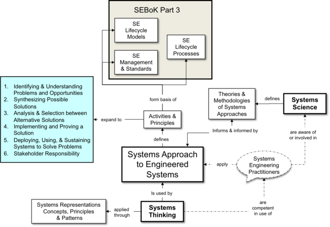
Figure 1. Systems Engineering and the Systems Approach. (SEBoK Original)
According to Jackson et al. (2010, 41-43), the systems approach to engineered systems is a problem-solving paradigm. It is a comprehensive problem identification and resolution approach based upon the principles, concepts, and tools of systems thinkingsystems thinking and systems sciencesystems science, along with the concepts inherent in engineering problem-solving. It incorporates a holistic systems view that covers the larger context of the system, including engineering and operational environments, stakeholders, and the entire life cycle.
Successful systems practice should not only apply systems thinking to the system being created but should also utilize systems thinking in consideration of the way in which work is planned and conducted. See Part 5: Enabling Systems Engineering for further discussions on how individuals, teams, businesses and enterprises may be enabled to perform systems engineering.
References
Works Cited
Jackson, S., D. Hitchins, and H. Eisner. 2010. "What is the Systems Approach?." INCOSE Insight, vol. 13, no. 1, pp. 41-43.
Primary References
Checkland, P. 1999. Systems Thinking, Systems Practice. New York, NY, USA: John Wiley & Sons.
Hitchins, D. 2009. "What are the General Principles Applicable to Systems?" INCOSE Insight, vol. 12, no. 4.
Jackson, S., D. Hitchins, and H. Eisner. 2010. "What is the Systems Approach?" INCOSE Insight, vol. 13, no. 1, pp. 41-43.
Additional References
Hitchins, D. 2007. Systems Engineering: A 21st Century Systems Methodology. Hoboken, NJ, USA: John Wiley & Sons.
Lawson, H. 2010. A Journey Through the Systems Landscape. London, UK: College Publications, Kings College.
Senge, P. M. 1990. The Fifth Discipline: The Art and Practice of the Learning Organization. New York, NY, USA: Doubleday/Currency.
< Previous Article | Parent Article | Next Article >
SEBoK v. 2.1, released 31 October 2019
