Difference between revisions of "Physical Architecture"
Afaisandier (talk | contribs) |
Wikiexpert (talk | contribs) |
||
| Line 205: | Line 205: | ||
</html> | </html> | ||
| − | |||
[[Category:Part 1]][[Category:Topic]] | [[Category:Part 1]][[Category:Topic]] | ||
[[Category:System Definition]] | [[Category:System Definition]] | ||
{{DISQUS}} | {{DISQUS}} | ||
Revision as of 21:22, 12 June 2012
The purpose of physical architecture design is to create a physical, concrete solution that accommodates the logical architecture and satisfies and trades-off system requirements. Once a logical architecture is defined (see Architectural Design: Logical), concrete physical elements have to be identified that could support functional, behavioral, and temporal features as well as expected properties of the system deduced from non-functional system requirements.
A physical architecture is an arrangement of physical elements (system elements and physical interfaces) which provides the design solution for a product, service, or enterprise, and is intended to satisfy logical architecture elements and system requirements (ISO/IEC 26702). It is implementable through technologies.
System Requirements are allocated to both the logical and physical architectures. The system architecture will be assessed during System Analysis and will become the basis for System Realization.
Concepts and Principles
Concepts of System Elements, Physical Interfaces, and Physical Architecture
A system element is a discrete part of a system that can be implemented to fulfill design properties. A system element can be hardware, software, data, humans, processes (e.g., processes that provide a service to users), procedures (e.g., operator instructions), facilities, materials, and naturally occurring entities (e.g., water, organisms, and minerals), or any combination of these (ISO/IEC 15288:2008).
A physical interface physically binds two system elements; this is similar to a link or a connector.
Table 1 provides some examples of system elements and physical interfaces.
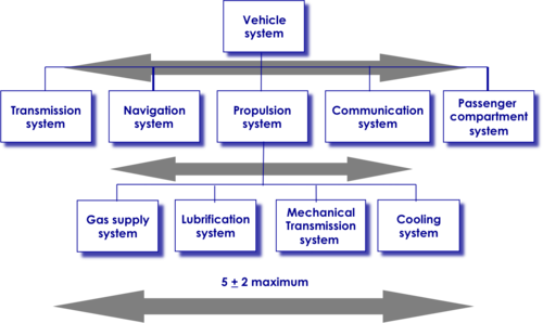
A complex system composed of thousands of physical and/or intangible parts may be structured in several layers of systems and system element. The number of elements in the decomposition of one system is limited to a few in order to facilitate the ease of mastering the system; generally "five plus or minus two" elements (see illustration in Figure 1).
Every system in each layer of the decomposition is structured as a physical architecture.
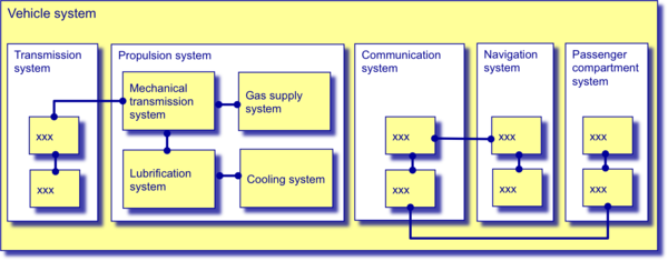
A physical architecture is built from systems, system elements, and all necessary physical interfaces between these elements, as well as from external elements (neighboring or enabling systems and/or system elements in the considered layer and concerned elements in the context of the global system of interest) - see illustration in Figure 2.
Concept of Design Property
A design property is a property obtained during design through the assignment of non-functional requirements, or estimates, analyses, calculations, simulations of a specific aspect, or obtained through the definition of an existing element associated with a system element, a physical interface, and/or a physical architecture. If the designed element complies with a requirement, the design property will relate to (or may equal) the requirement. Otherwise, one has to identify any discrepancy that could modify the requirement, the design, or identify a deviation.
Stakeholders have concerns that correspond to expected behavior within operational, environmental, or physical constraints as well as more general life cycle constraints. Stakeholders’ requirements and system requirements express these concerns as expected abilities from the system (e.g., usability, interoperability, security, expandability, environment suitability, etc.). Designers identify these abilities from requirements and deduce corresponding quantitative or qualitative design properties to equip their physical architecture (e.g., reliability, availability, maintainability, modularity, robustness, operability, climatic environment resistance, dimensions limits, etc.). (For more discussion on how these properties may be included in design, please see the Related Disciplines knowledge area (KA).
Emergent Properties
The overarching physical architecture of a system may have design properties that emerge from the the arrangement of and interaction between system elements, but which may not be properties of any individual element. emergence is the principle which states that entities exhibit properties which are meaningful only when attributed to the whole, not to its parts. Models of a human activity systems exhibit properties as a whole that are derived from its component activities and their structure, but cannot be reduced to them (Checkland 1999).
System elements interact between themselves and can create desirable or undesirable phenomena called emergent properties , such as inhibition, interference, resonance, or reinforcement of any property. The definition of the system includes an analysis of interactions between system elements in order to prevent undesirable properties and reinforce desirable ones.
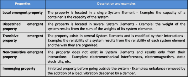
A property which emerges from a system can have various origins, from a single system element to several ones, or from interaction between several ones (Thome, B. 1993). (For more information, see Table 2, as well as the article by Dereck Hitchins at http://www.hitchins.net/EmergenceEtc.pdf.).
The notion of emergent properties is used during design to highlight necessary derived functions and internal physical or environmental constraints. Corresponding “derived requirements” should be added to the system requirements baseline when they impact the system of interest.
Allocation of Logical Elements to Physical Elements and Partitioning
Designing a candidate physical architecture for a system consists of first identifying system elements which can perform functions of the logical architecture and identify interfaces capable of carrying out input-output flows and control flows. When identifying potential elements, a systems engineer needs to allocate design properties within the logical architecture; these properties are deduced from system requirements. Partitioning and allocation are activities to decompose, gather, or separate functions in order to facilitate the identification of feasible system elements that support these functions. Either they exist and can be reused or re-purposed, or can be developed and technically implemented.
Partitioning and allocation use criteria to find potential affinities between functions. Designers use system requirements and/or design properties as criteria to assess and select physical candidate system elements and partitions of functions; e.g., similar transformations within the same technology, similar levels of efficiency, exchange of the same type of input-output flows (information, energy, and materials), centralized or distributed controls, execution with close frequency level, dependability conditions, environment resistance level, other enterprise constraints, etc.
Designing Physical Candidate Architectures
The goal of physical design activities is to provide the “best” possible physical architecture made of suitable system elements and physical interfaces (i.e., the architecture that answers, at best, all system requirements, depending on agreed limits or margins of each requirement). The best possible way to do this is to produce several candidate physical architectures, assess and compare them, and then select the most suitable one.
A candidate physical architecture is worked out according to affinity criteria in order to build a set of sub-systems and system elements (i.e., separate, gather, connect, and disconnect the network of system elements and their physical interfaces). These criteria are the same as those used for partitioning and allocating functions to system elements. The physical architecture design may be focused in different ways; some examples include:
- a reduction in the number of physical interfaces;
- system elements that can be tested separately;
- modular (i.e., have low interdependence);
- maintainable, replaceable system elements;
- compatible technology;
- measures of the proximity of elements in space;
- accounts of handling (weight, volume, and transportation facilities); or
- optimization of resources shared between elements.
Evaluating and Selecting the Preferred Candidate
Viable physical architectures enable all required functions or capabilities specified in the Logical Architecture.
Design activity includes optimization to obtain a balance among design properties, cost, risks, etc. Generally, the architecture of a system is determined more strongly by non-functional requirements (e.g., performance, safety, security, environmental conditions, constraints, etc.) than by functions. There may be many ways to achieve functions but fewer ways of satisfying non-functional requirements. The preferred physical architecture represents the optimized design after trade-offs are made.
Certain analyses (efficiency, dependability, cost, risks, etc.) are required to get sufficient data that characterize the global behavior of the candidate architectures regarding system requirements; this is often broadly referred to as “system analysis.”
Legacy Systems and Systems of Systems
When considering a set of existing systems of interest (SoI) that have their own existence in their own context of use, one issue is knowing whether or not it is possible to constitute a system of systems (SoS) that includes those existing systems as system elements (often called Component Systems). The higher level system has a mission, a purpose, a context of use, objectives, and architectural elements. Engineering of such systems generally includes both reverse engineering and a top down approach, as is the case when upgrading facilities in the frame of a company using information technology keeping legacy systems.
The architecture activity combines top-down and bottom-up approaches to integrate existing or legacy systems on which no (or very few) modifications can be applied. Additional tasks consist of identifying capabilities and interfaces of these existing systems. The architecture activity has to answer two questions:
- How can the requirements of the new system of interest be fulfilled?
- How can legacy systems be managed?
Please see the Systems of Systems (SoS) knowledge area (KA) for more information on special considerations for architecting a system of systems.
Process Approach
Purpose
The purpose of the physical architecture design process is to define, select, and synthesize a system physical architecture which can support the logical architecture. A physical architecture will have specific properties designed to address stakeholder or environmental issues and satisfy system requirements.
Because of the evolution of the context of use or technological possibilities, the physical architecture made of system elements is supposed to change along the life cycle of the system in order for it to continue to perform its mission within the limits of its required effectiveness. Depending on whether or not evolution impacts logical architecture elements, allocations to system elements could change. A physical architecture is equipped with specific design properties to continuously challenge the evolution.
Generic inputs include the selected logical architecture, system requirements, generic design patterns and properties that designers identify and use to answer requirements, outcomes from system analysis, and feedback from verification and validation.
Generic outputs are the selected physical architecture, allocation matrix of functional elements to physical elements, traceability matrix with system requirements, stakeholder requirements of each system and system elements composing the physical architecture, and rejected solutions.
Activities of the Process
Major activities and tasks to be performed during this process include the following:
- Partition and allocate functional elements to system elements:
- Search for system elements or technologies able to perform Functions, and physical interfaces to carry input-output and control Flows. Ensure system elements exist or can be engineered. Assess each potential system element using criteria deduced from design properties (themselves deduced from non-functional system requirements).
- Partition functional elements (functions, scenarios, input-outputs, triggers, etc.) using the given criteria, and allocate partitioned sets to system elements (using the same criteria).
- When it is impossible to identify a system element that corresponds to a partitioned functional set, decompose the function until the identification of implementable system elements is possible.
- Check the compatibility of technologies and the compatibility of interfaces between selected system elements.
- Model and design candidate physical architectures for each candidate:
- Because partitioned sets of functions can be numerous, there are generally too many system elements. For designing controllable architectures, system elements have to be grouped into higher-level system elements known as sub-systems.
- Constitute several different sets of sub-systems corresponding to different combinations of elementary system elements. One set of sub-systems plus one or several non-decomposable system elements form a candidate physical architecture of the considered system.
- Represent (using design patterns) the physical architecture of each sub-system connecting its system elements with physical interfaces that carry input-output Flows and triggers. Add physical interfaces as needed, in particular, add interfaces with external elements to the sub-system.
- Represent the synthesized physical architecture of the considered system built from sub-systems, system elements, and physical interfaces inherited from the physical architecture of sub-systems.
- Equip the physical architecture with design properties such as modularity, evolution capability, adaptability to different environments, robustness, scalability, resistance to environmental conditions, etc.
- If possible, use executable architecture prototypes(e.g. HW-SW in the loop prototypes) for identifying potential deficiencies, and correct the architecture as needed.
- Assess physical architecture candidates and select the most suitable one:
- Constitute a decision model based on criteria deduced from non-functional requirements (effectiveness, environmental conditions, safety, human factors, cost, risks, etc.) and design properties (modularity, communication commonality, maintainability, etc.)
- Assess physical architecture candidates against the given criteria. Select the most suitable one by comparing scores and rationales to determine which candidate best matches the criteria. Use the system analysis process to perform assessments (see the System Analysis Topic).
- Synthesize the selected physical architecture:
- Formalize physical elements and properties. Verify that system requirements are satisfied and that the solution is realistic.
- Identify the derived physical and functional elements created for the necessity of design and the corresponding system requirements.
- Establish traceability between system requirements and physical elements, as well as allocation matrices between functional and physical elements.
- Prepare for the acquisition of each system or system element:
- Define the system or system element’s mission and objectives from allocated functions and effectiveness.
- Define the stakeholder requirements (the concerned stakeholder being the current studied system). Additional information about development of stakeholder requirements can be found in the Stakeholders Requirements topic.
- Establish traceability between the stakeholder requirements and design elements of the studied system. This allows traceability of requirements between two layers of systems.
Artifacts and Ontology Elements
This process may create several artifacts, such as:
- system design documents (describe selected logical and physical architectures);
- system design justification documents (traceability matrices and design choices); and
- system element stakeholder requirements documents (one for each system or system element).
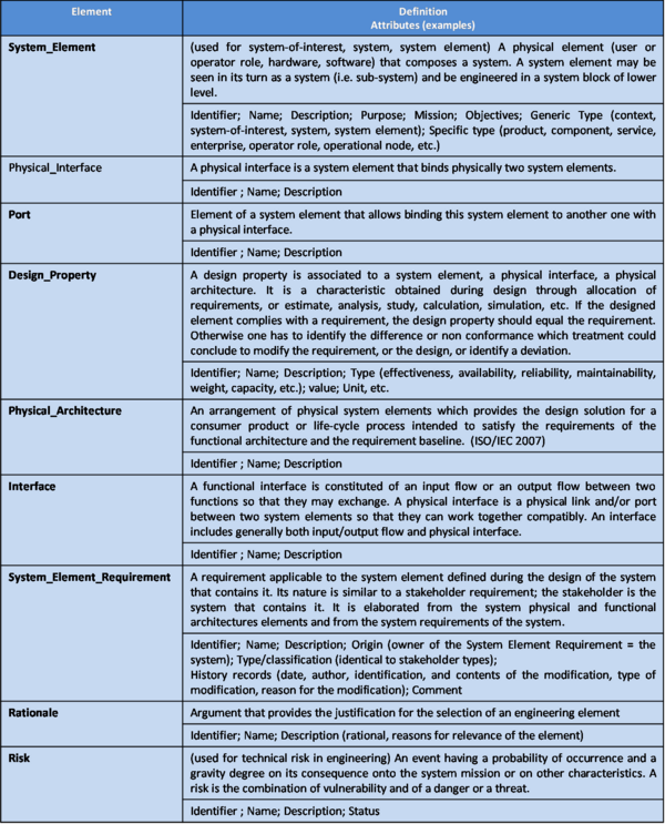
This process handles the ontology elements of Table 3.
Note: The element "Interface" may include both functional and physical aspects. It can be used for technical management purposes.
Note: System element requirements become stakeholder requirements applicable to the system element of the lower layer of decomposition.
Methods and Modeling Techniques
Modeling techniques are often used in architecture design. Some common models used in architectural design include:
- Physical block diagrams (PBD);
- SysML block definition diagrams (BDD); or
- Internal block diagrams (IBD) (OMG 2010);
- Executable architecture prototyping.
Practical Considerations
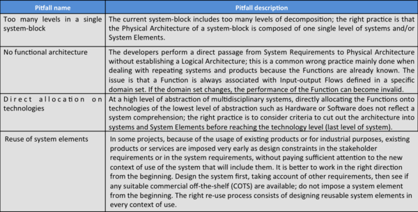
Major pitfalls encountered with physical architecture design are presented in Table 4.
Proven practices with physical architecture design are presented in Table 5.
References
Citations
Checkland, P. B. 1999. Systems Thinking, Systems Practice. Chichester, UK: John Wiley & Sons Ltd.
ISO/IEC. 2007. Systems Engineering – Application and Management of The Systems Engineering Process. Geneva, Switzerland: International Organization for Standards (ISO)/International Electronical Commission (IEC), ISO/IEC 26702:2007.
OMG. 2010. OMG Systems Modeling Language specification, version 1.2, July 2010. http://www.omg.org/technology/documents/spec_catalog.htm.
Thome, B. 1993. Systems Engineering, Principles & Practice of Computer-Based Systems Engineering. New York, NY, USA: Wiley.
Primary References
ANSI/IEEE. 2000. Recommended practice for architectural description for software-intensive systems. New York, NY: American National Standards Institute (ANSI)/Institute of Electrical and Electronics Engineers (IEEE), ANSI/IEEE 1471-2000.
INCOSE. 2011. INCOSE Systems Engineering Handbook: A Guide for System Life Cycle Processes and Activities, version 3.2.1. San Diego, CA, USA: International Council on Systems Engineering (INCOSE), INCOSE-TP-2003-002-03.2.1.
ISO/IEC/IEEE. 2008. Systems and Software Engineering - System Life Cycle Processes. Geneva, Switzerland: International Organization for Standardization (ISO)/International Electronical Commission (IEC), Institute of Electrical and Electronics Engineers. ISO/IEC/IEEE 15288:2008 (E).
ISO/IEC/IEEE. 2011. Systems and Software Engineering - Architecture Description. Geneva, Switzerland: International Organization for Standardization (ISO)/International Electrotechnical Commission (IEC)/Institute of Electrical and Electronics Engineers (IEEE), ISO/IEC/IEEE 42010.
Maier, M., and E. Rechtin. 2009. The Art of Systems Architecting. 3rd ed. Boca Raton, FL, USA: CRC Press.
Additional References
Faisandier, A. 2012 (in press). Engineering and Architecting Multidisciplinary Systems.
Thome, B. 1993. Systems Engineering, Principles & Practice of Computer-Based Systems Engineering. New York, NY, USA: Wiley.
Comments from SEBoK 0.5 Wiki
Please note that in version 0.5, this article was titled “Architectural Design”. The comments below are shared with the "Architectural Design: Logical" article.
<html> <iframe src="http://www.sebokwiki.org/05/index.php?title=Talk:Architectural_Design&printable=yes" width=825 height=200 frameborder=1 scrolling=auto> </iframe> </html>
SEBoK Discussion
Please provide your comments and feedback on the SEBoK below. You will need to log in to DISQUS using an existing account (e.g. Yahoo, Google, Facebook, Twitter, etc.) or create a DISQUS account. Simply type your comment in the text field below and DISQUS will guide you through the login or registration steps. Feedback will be archived and used for future updates to the SEBoK. If you provided a comment that is no longer listed, that comment has been adjudicated. You can view adjudication for comments submitted prior to SEBoK v. 1.0 at SEBoK Review and Adjudication. Later comments are addressed and changes are summarized in the Letter from the Editor and Acknowledgements and Release History.
If you would like to provide edits on this article, recommend new content, or make comments on the SEBoK as a whole, please see the SEBoK Sandbox.
blog comments powered by Disqus
