File list
Jump to navigation
Jump to search
This special page shows all uploaded files.
| Date | Name | Thumbnail | Size | User | Description | Versions |
|---|---|---|---|---|---|---|
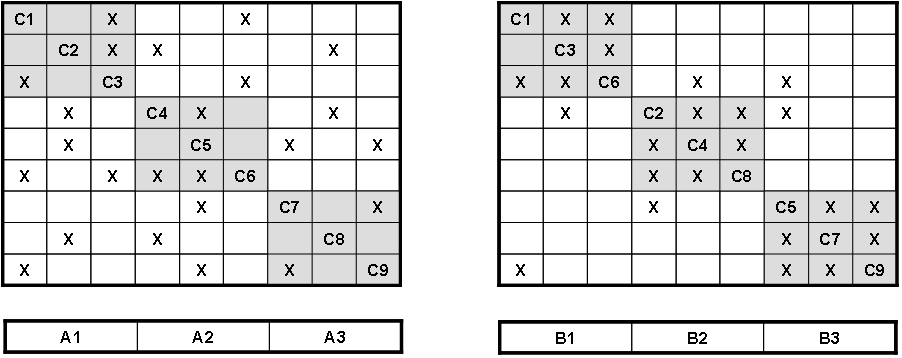
| 18:37, 23 June 2011 | JS Figure 9.png (file) |  |
12 KB | Smenck2 | Figure. Initial arrangement of aggregates on the left; final arrangement after reorganization on the right (SOURCE, YEAR/Permission Pending) | 1 |
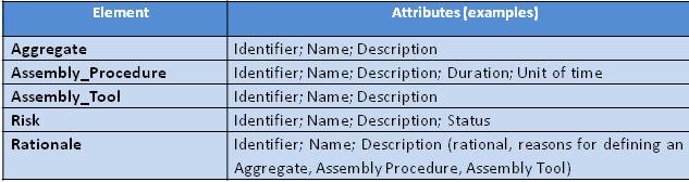
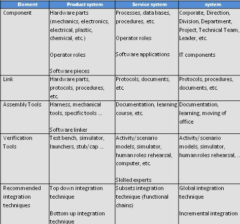
| 18:38, 23 June 2011 | JS Table 1.png (file) | 12 KB | Smenck2 | Table. Main ontology elements as handled within system integration (SOURCE, YEAR/Permission Pending) | 1 | |
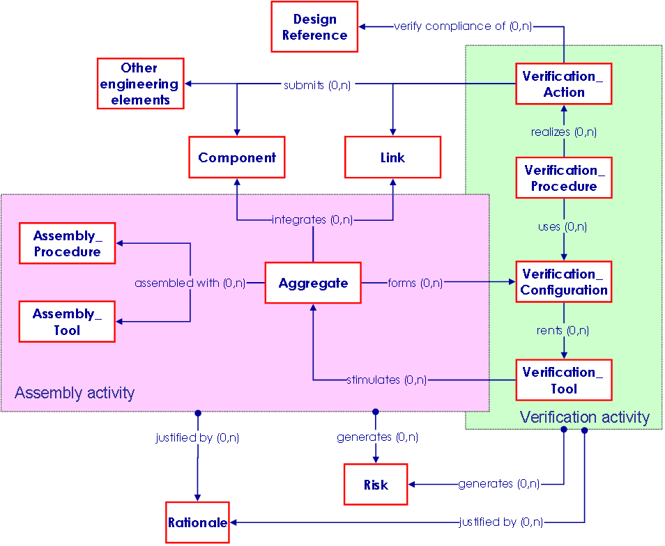
| 18:45, 23 June 2011 | JS Figure 8.png (file) |  |
26 KB | Smenck2 | Figure. Integration elements relationships with other engineering elements (SOURCE, YEAR/Permission Pending) | 1 |
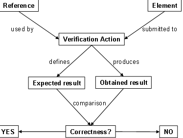
| 18:46, 23 June 2011 | JS Figure 10.png (file) |  |
9 KB | Smenck2 | Figure. Definition and usage of a Verification Action (SOURCE, YEAR/Permission Pending) | 1 |
| 18:47, 23 June 2011 | JS Table2.png (file) |  |
20 KB | Smenck2 | Table. Main ontology elements as handled within verification (SOURCE, YEAR/Permission Pending) | 1 |
| 18:48, 23 June 2011 | JS Figure 11.png (file) |  |
33 KB | Smenck2 | Figure. Verification elements relationships with other engineering elements (SOURCE, YEAR/Permission Pending) | 1 |
| 18:48, 23 June 2011 | JS Figure 12.png (file) |  |
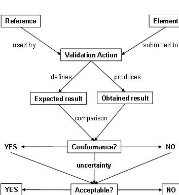
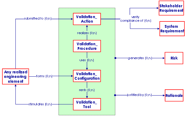
11 KB | Smenck2 | Figure. Definition and usage of a Validation Action (SOURCE, YEAR/Permission Pending) | 1 |
| 18:50, 23 June 2011 | JS Figure 13.png (file) |  |
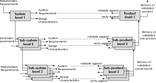
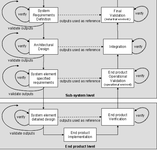
15 KB | Smenck2 | Figure. Verification and Validation level by level (SOURCE, YEAR/Permission Pending) | 1 |
| 18:50, 23 June 2011 | JS Figure 14.png (file) |  |
28 KB | Smenck2 | Figure. Verification and Validation Actions in upper levels of system decomposition (SOURCE, YEAR/Permission Pending) | 1 |
| 18:51, 23 June 2011 | JS Figure 15.png (file) |  |
29 KB | Smenck2 | Figure. Verification and Validation Actions in lower levels of system decomposition (SOURCE, YEAR/Permission Pending) | 1 |
| 18:52, 23 June 2011 | JS Figure 16.png (file) |  |
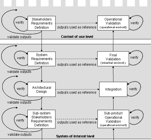
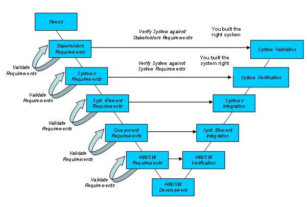
26 KB | Smenck2 | Figure. Validation throughout the System Life Cycle (shown on a Vee Model) (Source: EADS, /Used with Permission) | 1 |
| 18:54, 23 June 2011 | JS Table3.png (file) |  |
15 KB | Smenck2 | Table. Main ontology elements as handled within validation (SOURCE, YEAR/Permission Pending) | 1 |
| 18:57, 23 June 2011 | JS Figure 17.png (file) |  |
15 KB | Smenck2 | Figure. Validation elements relationships with other engineering elements (SOURCE, YEAR/Permission Pending) | 1 |
| 19:51, 23 June 2011 | JSTable vvcomparison.png (file) |  |
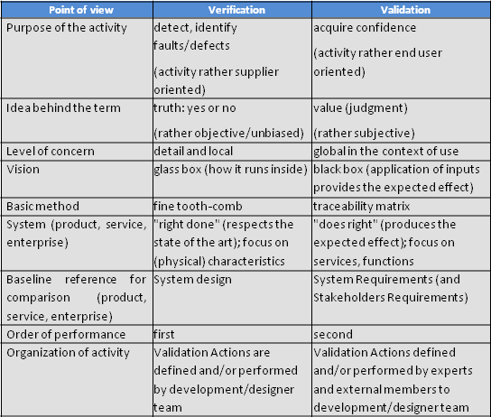
30 KB | Smenck2 | Table. Comparison (SOURCE, YEAR/Permission Pending) | 1 |
| 19:58, 23 June 2011 | JS Table 5.png (file) |  |
15 KB | Smenck2 | Table. Comparison (SOURCE, YEAR/Permission Pending) | 1 |
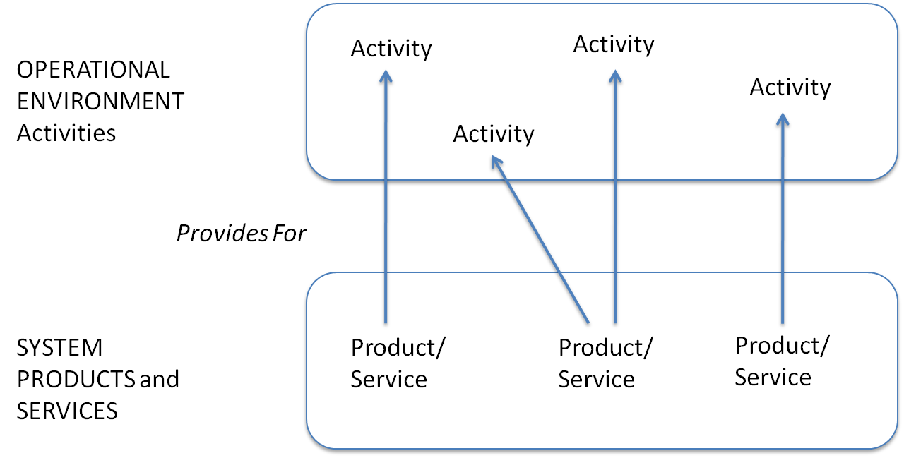
| 15:53, 28 June 2011 | 062611 BL Product Services Provisioning Paradigm.png (file) |  |
47 KB | Smenck2 | Figure. Product/Service Provisioning (Figure Developed for BKCASE) | 1 |
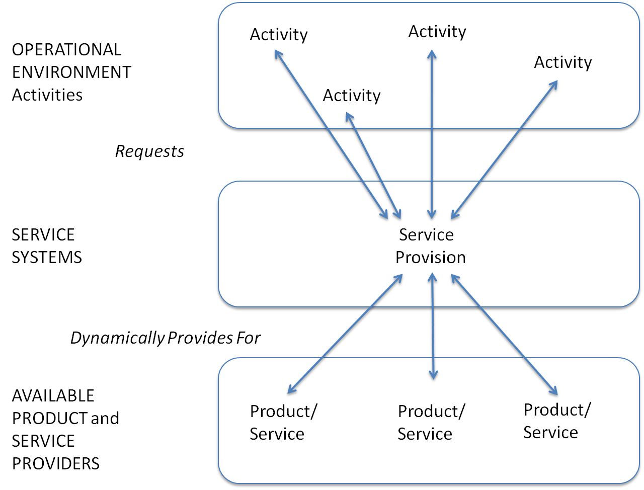
| 15:56, 28 June 2011 | 062611 BL Service Systems Paradigm.png (file) |  |
90 KB | Smenck2 | Figure. Service System Provisioning (Figure Developed for BKCASE) | 1 |
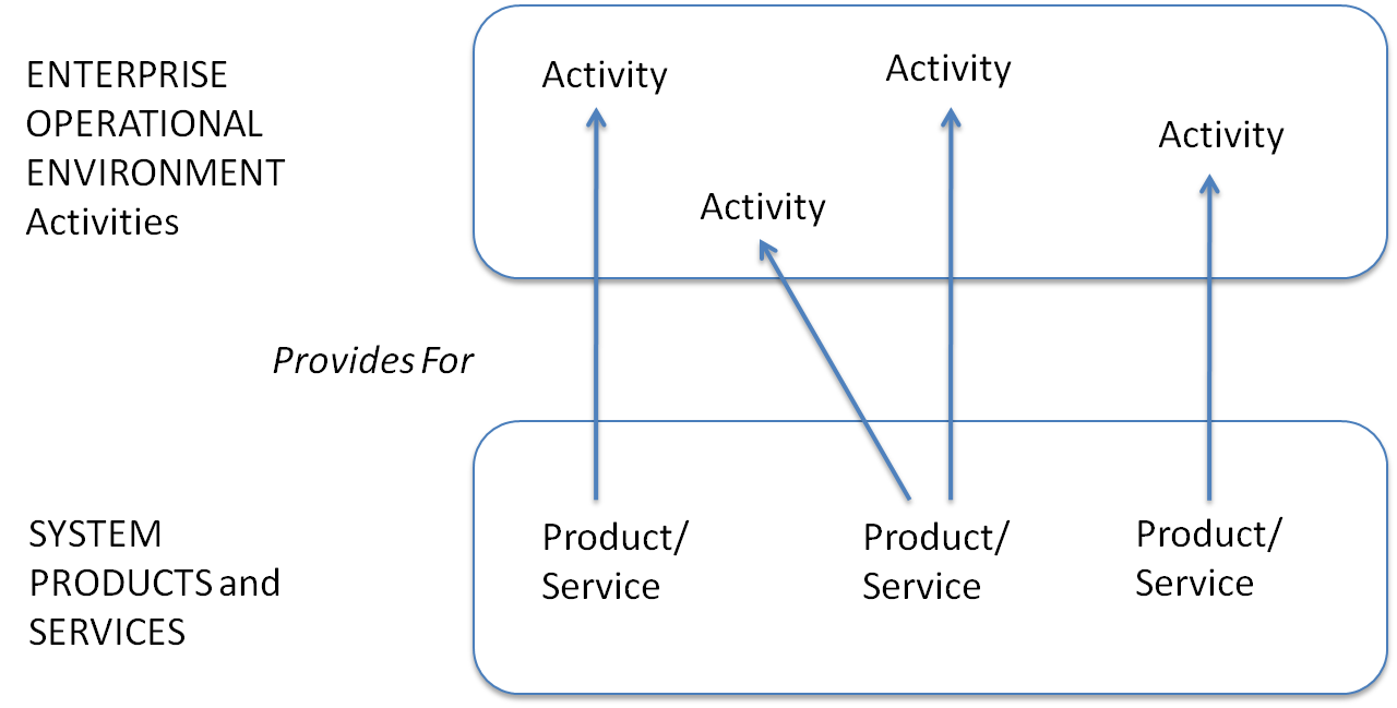
| 15:57, 28 June 2011 | 062611 BL Engineering of an Enterprise Paradigm.png (file) |  |
48 KB | Smenck2 | Figure. Engineering of an Enterprise (Figure Developed for BKCASE) | 1 |
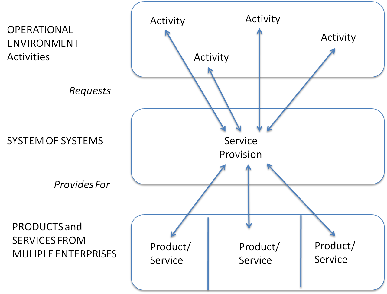
| 15:58, 28 June 2011 | 062611 BL Systems of Systems Paradigm.png (file) |  |
93 KB | Smenck2 | Figure. System of Systems Provisioning (Figure Developed for BKCASE) | 1 |
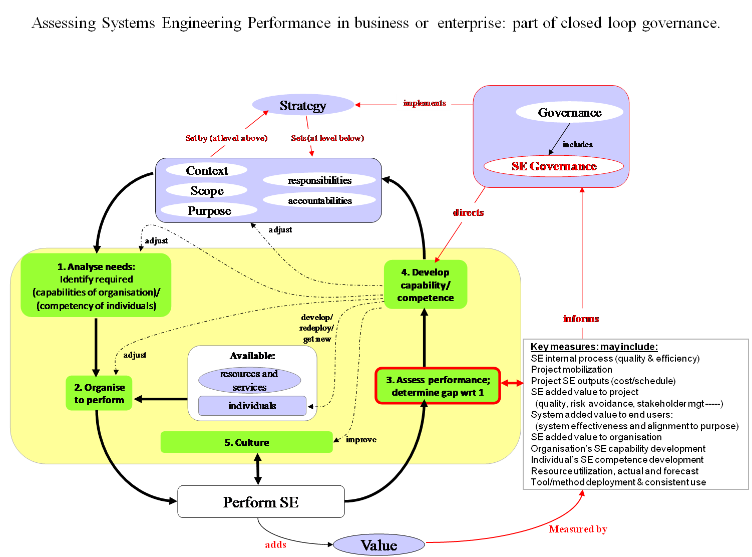
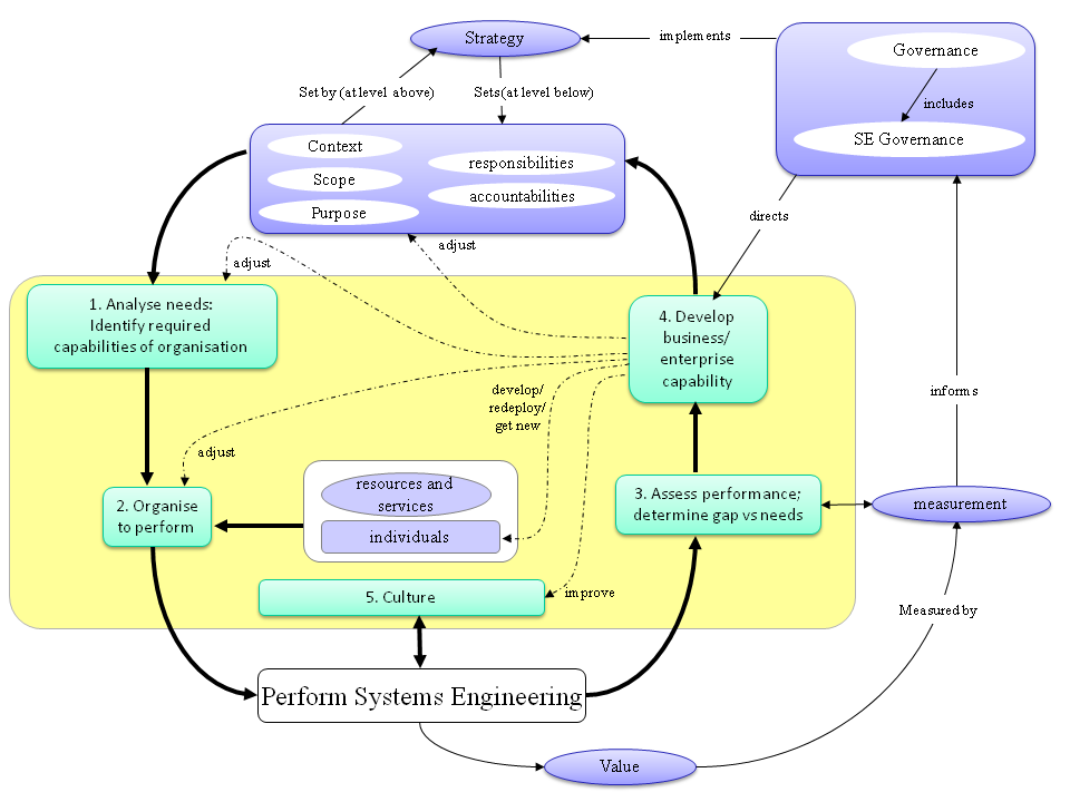
| 21:14, 13 July 2011 | Picture1 HGS.png (file) |  |
323 KB | Smenck2 | Figure. Assessing systems engineering performance in business or enterprise: part of closed loop governance (Figure Developed for BKCASE) | 3 |
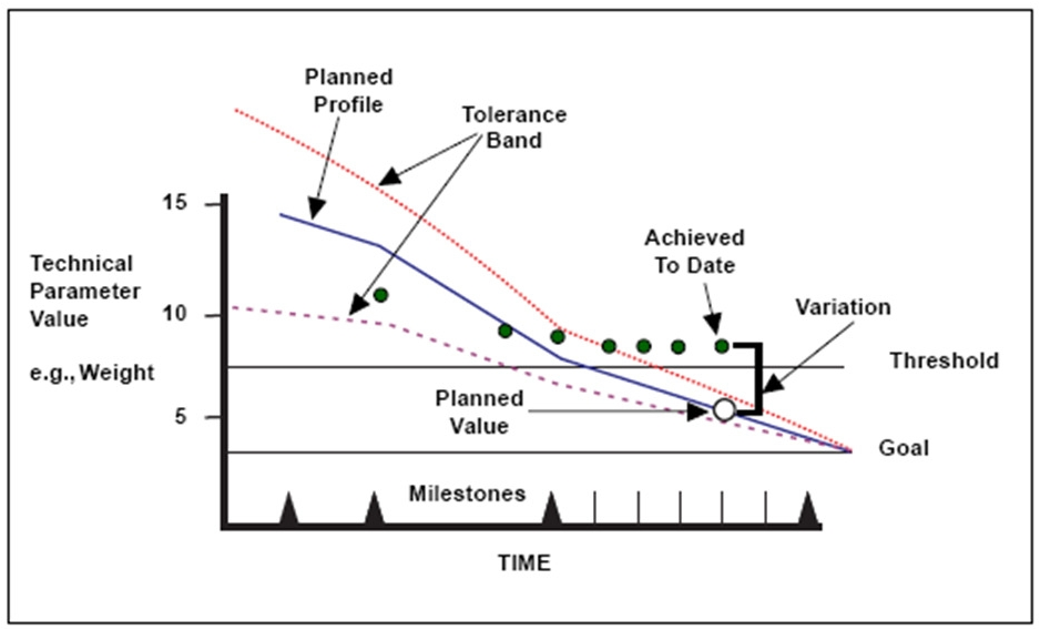
| 21:24, 13 July 2011 | TPM Chart from INCOSE SELIG.png (file) |  |
135 KB | Smenck2 | Figure. Technical Performance Measure (TPM) Tracking (Source: Roedler, Rhodes, Schimoller, Jones, 2010/ Permission Pending) | 1 |
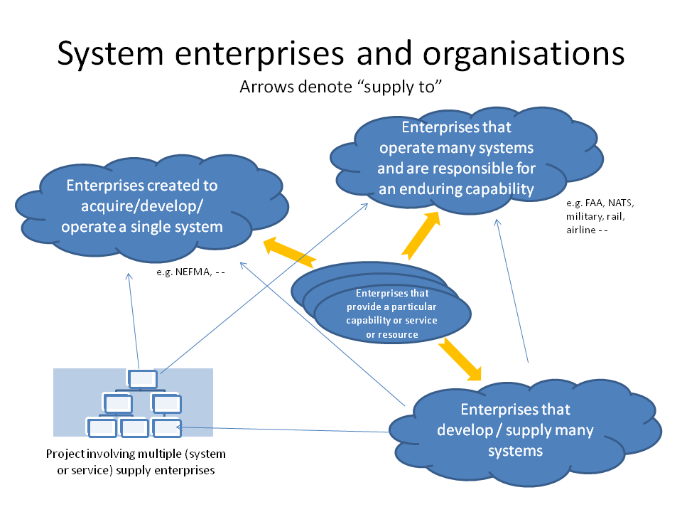
| 21:31, 13 July 2011 | System enterprises and organizations.png (file) |  |
61 KB | Smenck2 | Figure. Systems Enterprises and Organizations (Figure Developed for BKCASE) | 1 |
| 21:35, 13 July 2011 | Concept map for businesses and enterprises topics.png (file) |  |
68 KB | Smenck2 | Figure. Concept Map for Businesses and Enterprises Topics (Figure Developed for BKCASE) | 1 |
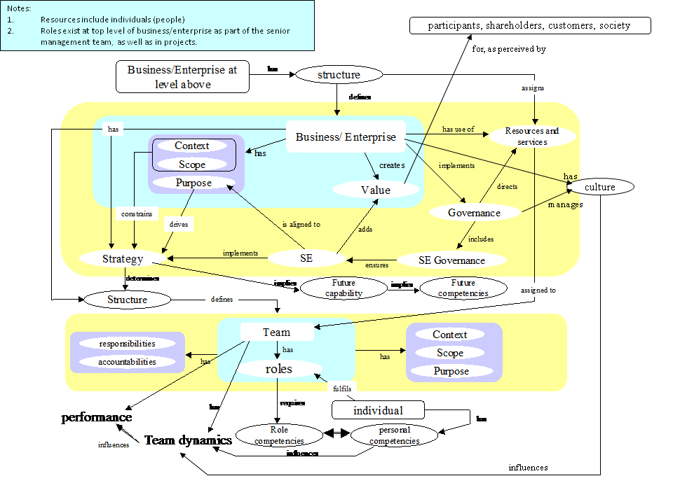
| 21:38, 13 July 2011 | Businesses, teams and individuals in SE.png (file) |  |
43 KB | Smenck2 | Figure. Businesses, Teams and Individuals in SE (Figure Developed for BKCASE) | 1 |
| 16:09, 14 July 2011 | IPT-System Mapping Diagram.png (file) |  |
25 KB | Smenck2 | Figure. IPT-System Mapping Diagram (Figure Developed for BKCASE) | 1 |
| 17:51, 14 July 2011 | Fig. 1 Integration Process for Specialty Engineering.png (file) |  |
160 KB | Smenck2 | Figure. Integration Process for Specialty Engineering (Source: US Air Force, 2000/Released) | 1 |
| 17:55, 14 July 2011 | Figure 1. System Safety Process.png (file) |  |
133 KB | Smenck2 | Figure. System Safety Process (Source: Unknown/Permission Pending) | 1 |
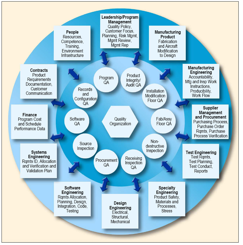
| 17:56, 14 July 2011 | Interactions for Quality Control Processes.png (file) |  |
642 KB | Smenck2 | Figure. Interactions for Quality Control Processes (Source: Unknown/Permission Pending) | 1 |
| 18:22, 20 July 2011 | SEBoKv05 KA-SystDef A simplified meta-data model for system development.png (file) |  |
63 KB | Smenck2 | A simplified view of a meta-data model for system development. (Source: Faisandier 2011/Used with Permission) © Alain Faisandier-2011 | 1 |
| 18:23, 20 July 2011 | SEBoKv05 KA-SystDef A simplified ontology for System Definition.png (file) |  |
63 KB | Smenck2 | A simplified ontology for System Definition. (Source: Faisandier 2011/Used with Permission) © Alain Faisandier-2011 | 1 |
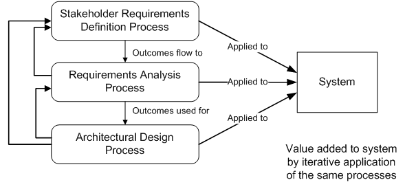
| 18:24, 20 July 2011 | SEBoKv05 KA-SystDef Example of iterations of processes related to System Definition.png (file) |  |
17 KB | Smenck2 | Figure. Example of iterations of processes related to System Definition (Source: ISO, 2003/Permission Pending) | 1 |
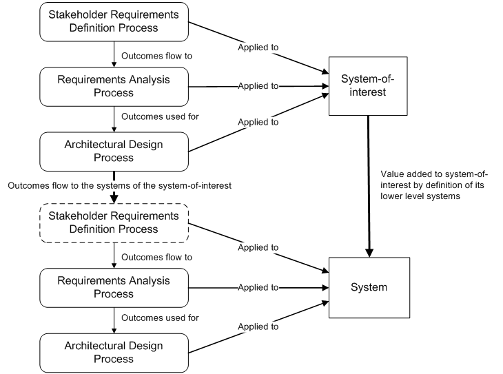
| 18:26, 20 July 2011 | SEBoKv05 KA-SystDef Recursion of processes on layers.png (file) |  |
34 KB | Smenck2 | Figure. Example of iterations of processes related to System Definition (Source: ISO, 2003/Permission Pending) | 1 |
| 23:23, 31 July 2011 | Stages of Group Development.png (file) |  |
1.97 MB | Janthony | Proprietary Forsyth, D.R. (2010) Group Dynamics (5th ed.) Belmont, CA: Wadsworth, Cengage Learning. p.20, Modified Figure 1.5 | 3 |
| 19:17, 3 August 2011 | SEBoKv05 KA-SystDef Example of states of a requirement.png (file) |  |
6 KB | Smenck2 | Figure. Example of States of a Requirement (Figure Developed for BKCASE) | 1 |
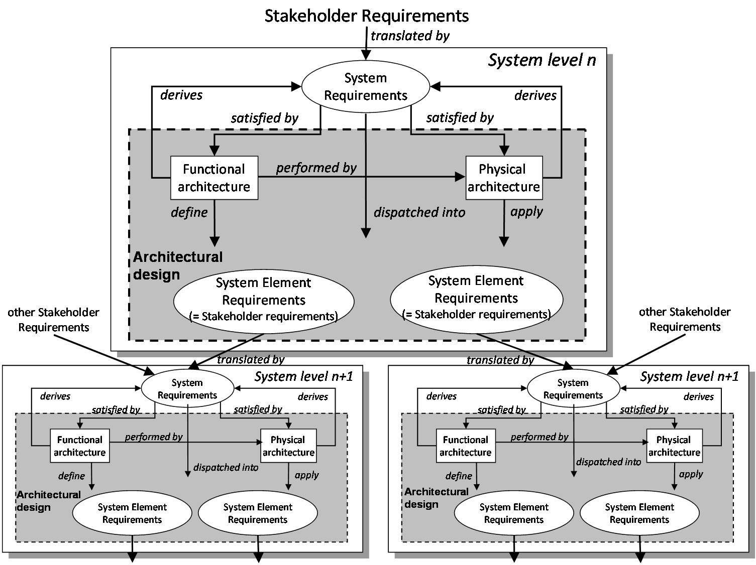
| 19:19, 3 August 2011 | SEBoKv05 KA-SystDef Recursive instantiation of Definition process.png (file) |  |
96 KB | Smenck2 | Figure. Recursive Instantiation of Definition Process (Figure Developed for BKCASE) | 1 |
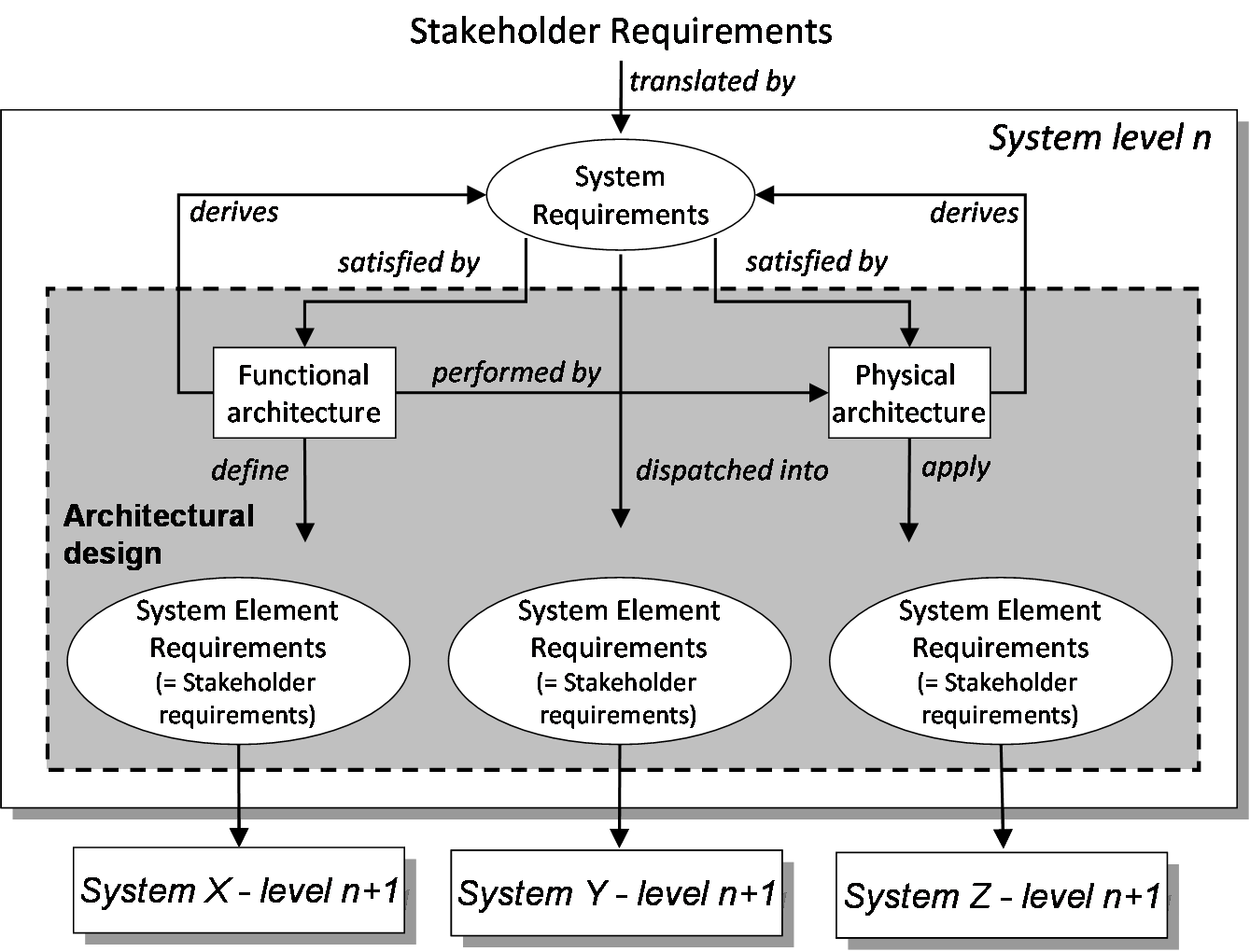
| 19:41, 3 August 2011 | SEBoKv05 KA-SystDef Requirements and Design in each system block.png (file) |  |
66 KB | Smenck2 | Figure. Requirements and Design in Each System Block (Figure Developed for BKCASE) | 1 |
| 19:42, 3 August 2011 | SEBoKv05 KA-SystDef Top-down development of design and requirements.png (file) |  |
124 KB | Smenck2 | Figure. Top-down Development of Design and Requirements (Figure Developed for BKCASE) | 1 |
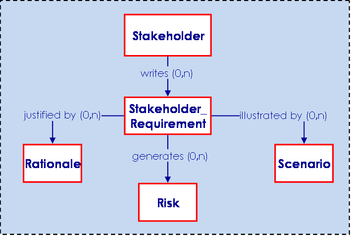
| 21:05, 3 August 2011 | SEBoKv05 KA-SystDef Stakeholder Requirements relationships.png (file) |  |
11 KB | Smenck2 | Figure. Stakeholder Requirements Relationships with Other Engineering Elements(Source: Faisandier 2011/Used with Permission) © Alain Faisandier-2012 | 1 |
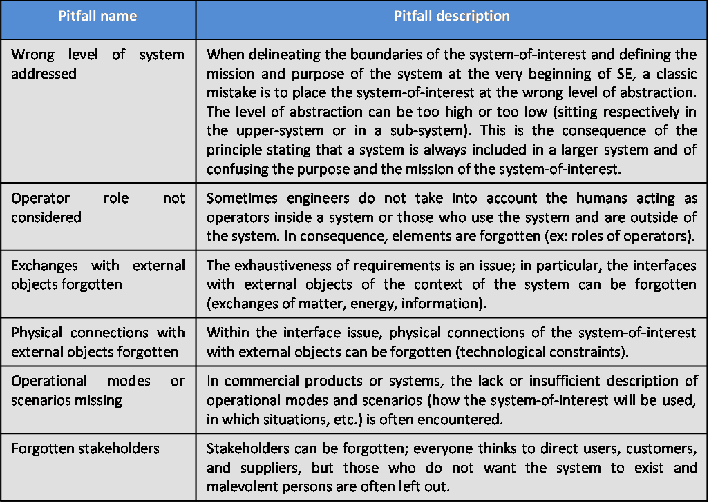
| 21:08, 3 August 2011 | SEBoKv05 KA-SystDef pitfalls Stakeholder Requirements.png (file) |  |
59 KB | Smenck2 | Table. Major Pitfalls with Definition of Stakeholder Requirements (Table Developed for BKCASE) | 1 |
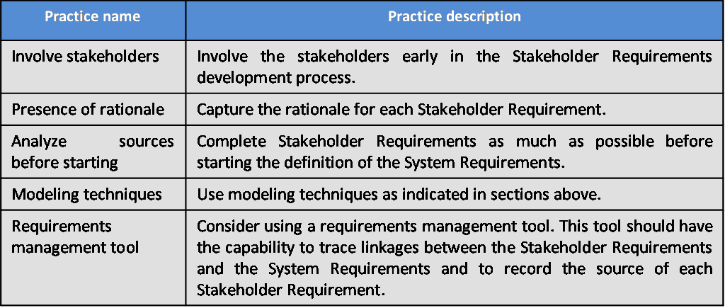
| 21:09, 3 August 2011 | SEBoKv05 KA-SystDef practices Stakeholder Requirements.png (file) |  |
29 KB | Smenck2 | Table. Proven Practices with Definition of Stakeholder Requirements (Table Developed for BKCASE) | 1 |
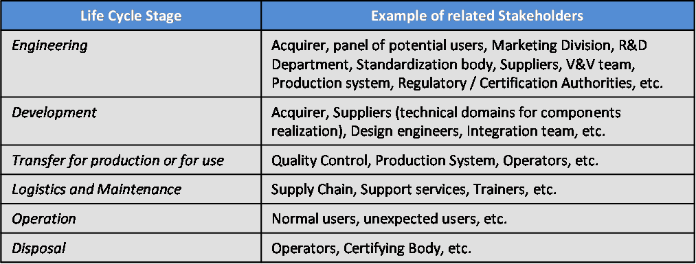
| 21:26, 3 August 2011 | SEBoKv05 KA-SystDef Stakeholders Identification Based on Life.png (file) |  |
29 KB | Smenck2 | Table. Stakeholders Identification Based on Life Cycle Stages (Table Developed for BKCASE) | 1 |
| 01:05, 4 August 2011 | SEBoKv05 KA-SystDef System Requirements relationships.png (file) |  |
13 KB | Smenck2 | Figure. System Requirements Relationships with Other Engineering Elements (Source: Faisandier 2011/Used with Permission) © Alain Faisandier-2012 | 1 |
| 01:11, 4 August 2011 | SEBoKv05 KA-SystDef Characteristics of a set of Requirements.png (file) |  |
45 KB | Smenck2 | Table. Characteristics of a Set of Requirements (Source: ISO, 2011/Permission Pending) | 1 |
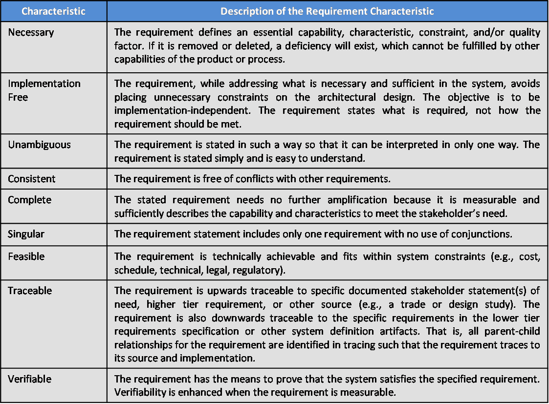
| 01:12, 4 August 2011 | SEBoKv05 KA-SystDef Characteristics of Individual Requirements.png (file) |  |
68 KB | Smenck2 | Table. Characteristics of Individual Requirements (Source: ISO, 2011/Permission Pending) | 1 |
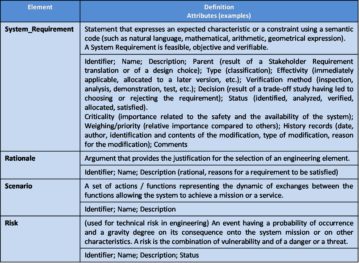
| 01:12, 4 August 2011 | SEBoKv05 KA-SystDef ontology elements system requirements.png (file) |  |
74 KB | Smenck2 | Table. Main Ontology Elements as Handled within System Requirements Definition (Figure Developed for BKCASE) | 1 |
| 01:13, 4 August 2011 | SEBoKv05 KA-SystDef pitfalls System Requirements.png (file) |  |
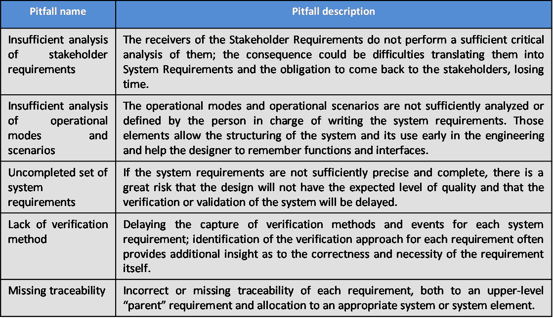
52 KB | Smenck2 | Table. Major Pitfalls with Definition of System Requirements (Figure Developed for BKCASE) | 1 |
| 01:13, 4 August 2011 | SEBoKv05 KA-SystDef practices System Requirements.png (file) |  |
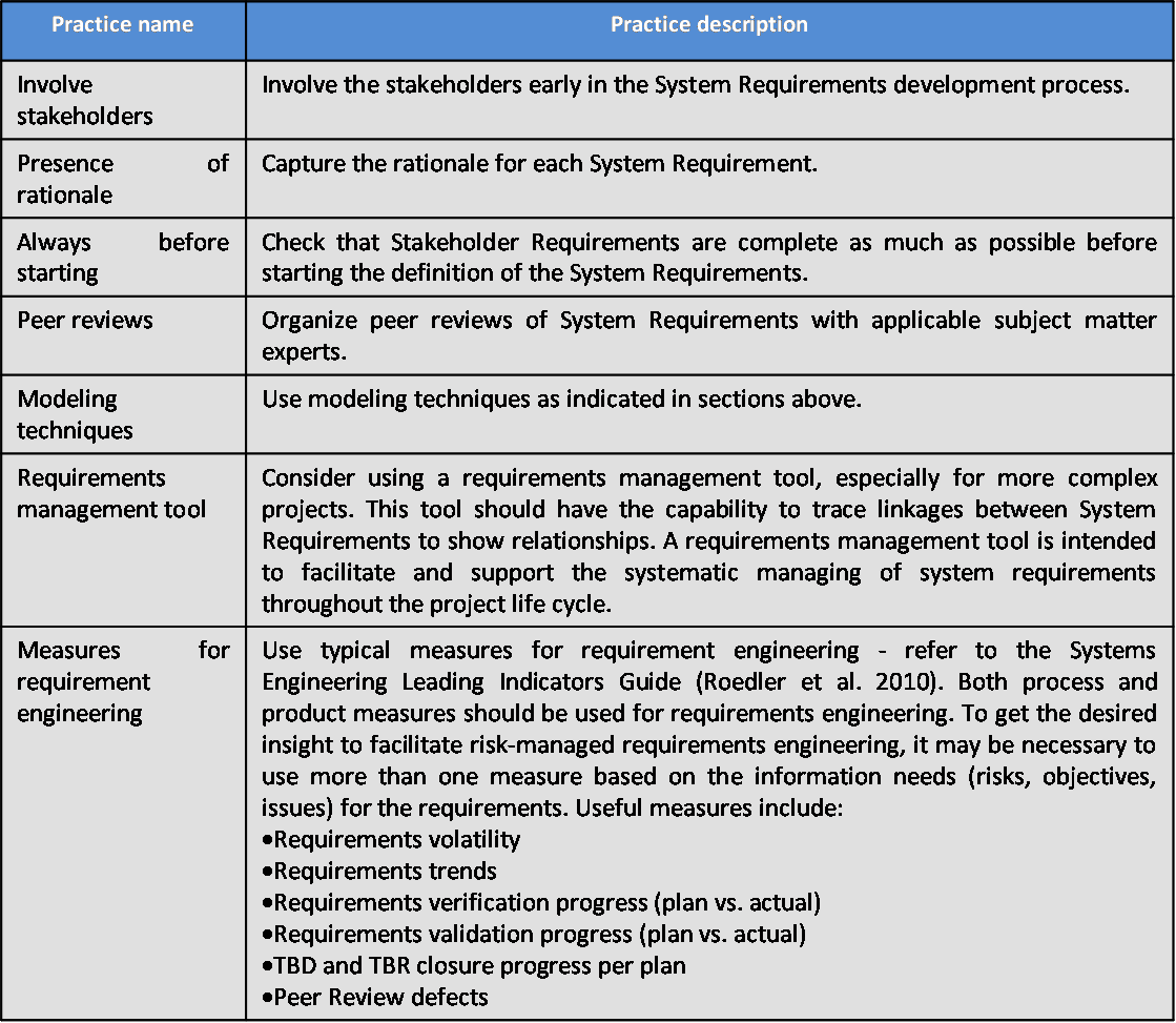
72 KB | Smenck2 | Table. Proven Practices with Definition of System Requirements(Figure Developed for BKCASE) | 1 |
| 02:13, 4 August 2011 | SEBoKv05 KA-SystDef Complete Interface Representation.png (file) |  |
17 KB | Smenck2 | Figure. Complete Interface Representation (Source: Faisandier 2011/Used with Permission) © Alain Faisandier-2011 | 1 |
| 02:14, 4 August 2011 | SEBoKv05 KA-SystDef Functional Design relationships.png (file) |  |
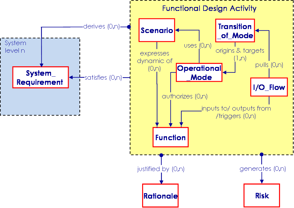
26 KB | Smenck2 | Figure. Functional Design Elements Relationships with Other Engineering Elements (Source: Faisandier 2011/Used with Permission) © Alain Faisandier-2011 | 1 |
| 02:14, 4 August 2011 | SEBoKv05 KA-SystDef Intellectual creation principles.png (file) |  |
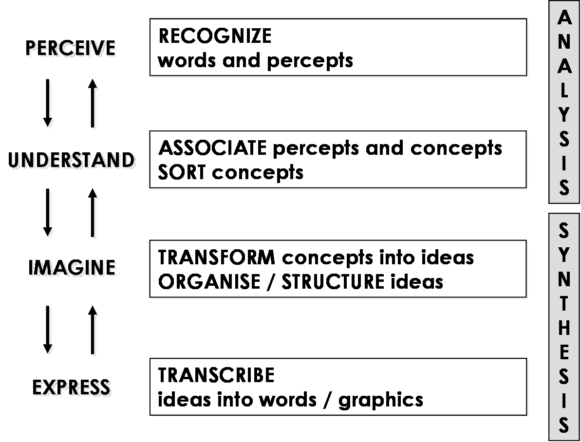
49 KB | Smenck2 | Figure. Intellectual Creation Principles and Mechanism (Source: Faisandier 2011/Used with Permission) © Alain Faisandier-2011 | 1 |