Uncategorized files
Jump to navigation
Jump to search
Showing below up to 250 results in range #251 to #500.
View (previous 250 | next 250) (20 | 50 | 100 | 250 | 500)
 KF GenericLifeCycleStages.png 468 × 205; 33 KB
 KF GenericStageStructure.png 417 × 316; 57 KB
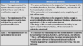
 KF ICSMActivityCategories.png 468 × 515; 97 KB
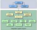
 KF ILSSupportingSystem.png 445 × 232; 38 KB
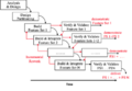
 KF ILSSystemLifeCycle.png 377 × 303; 41 KB
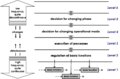
 KF Incremental&EvolDecision.png 450 × 265; 34 KB
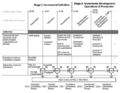
 KF Incremental&EvolDevelopment.png 468 × 209; 52 KB
 KF IncrementalBuildCycles.png 433 × 299; 46 KB
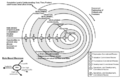 KF IncrementalCommitmentSpiral.png 455 × 296; 54 KB
 KF IncrementalDevelopment Multiple.png 468 × 332; 48 KB
 KF IncrementalDevelopment Single.png 468 × 358; 45 KB
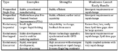
 KF LifeCycleComparisons.png 468 × 433; 94 KB
 KF PartitioningCriteria.png 468 × 115; 22 KB
 KF Phase GenericIncremental.png 469 × 363; 64 KB
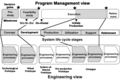 KF ProgramManagement&EngineeringViews.png 358 × 240; 37 KB
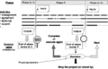 KF SchedulingDevelopment.png 412 × 265; 29 KB
 KF SoftwareDevelopmentEmphasis.png 468 × 122; 22 KB
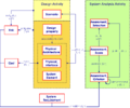
 KF VeeModel DesignConcept.png 451 × 363; 118 KB
 KF VeeModel ExploratoryResearch.png 441 × 360; 76 KB
 KF VeeModel Left.png 830 × 618; 118 KB
 KF VeeModel Right.png 731 × 571; 107 KB
 LDSE Figure 20200702.gif 2,000 × 1,500; 97 KB
 LM logo Blue notag.200.png 200 × 200; 5 KB
 LM logo Blue notag.png 500 × 121; 2 KB
 Layered and Multi-dimensional in the Engineering Layer.PNG 512 × 384; 18 KB
 Le Ha Phuong.jpg 1,863 × 2,609; 774 KB
 Life-Cycle-Model-Purpose AdaptedfromIEEE Dove.png 733 × 712; 212 KB
 Limits of integration activities.png 609 × 642; 18 KB
 Logo SEBoK 10th.png 1,966 × 987; 431 KB
 Loss Driven Systems Engineering Figure 1.png 624 × 383; 15 KB
 MBSE Trends Figure 1.png 1,027 × 533; 22 KB
 MBSE Trends Figure 2.png 761 × 460; 17 KB
 MBSE Trends Figure 3.png 1,473 × 764; 89 KB
 MBSE Trends Figure 4.png 1,008 × 534; 96 KB
 MBSE Trends Figure 5.png 855 × 474; 43 KB
 MBSE Trends Figure 6.png 1,111 × 609; 37 KB
 MBSE Trends Figure 7.png 1,115 × 688; 27 KB
 MBSE Trends Figure 8.png 1,163 × 790; 67 KB
 MITRE Enterprise Systems Engineering Framework.PNG 625 × 384; 147 KB
 Main ontology elements as handled within validation.png 772 × 1,018; 396 KB
 Main ontology elements as handled within verification.png 769 × 1,040; 406 KB
 Major pitfalls with System Validation.png 964 × 667; 190 KB
 Major pitfalls with System Verification.png 964 × 957; 286 KB
 Major technical reviews.png 1,234 × 1,036; 359 KB
 Mapping of tech topics SEBoK with ISO IEC 15288techPro 060612.jpg 761 × 532; 121 KB
 Measurement Process Model-Figure 1.png 960 × 720; 36 KB
 Mediawiki and Caching.pdf ; 54 KB
 MissionAndCapabilities.png 1,486 × 783; 151 KB
 Missouri-S T PrimaryLogo Apple.png 1,157 × 940; 27 KB
 Model-Based System Design Process Part3.png 1,262 × 843; 171 KB
 NASA Image Part 1.png 974 × 663; 122 KB
 Needs-to-requirements-ryan.PNG 960 × 713; 74 KB
 One Spin of the Holon.jpg 960 × 720; 101 KB
 Organizational coupling diagram v2.png 962 × 577; 154 KB
 P1 EconValueSE RiskBalancedfig2 BB.jpg 327 × 403; 21 KB
 P1 Scope and Con SE and Eng Sys Proj LF BB.jpg 1,362 × 845; 145 KB
 P1 Scope and Con SEbok LC and Cont Related Agents BB.jpg 1,205 × 869; 134 KB
 P6 Fig1 The Organizational Continuum KN.jpg 1,166 × 597; 47 KB
- PDFCoverPage P7.pdf ; 9.81 MB
 PM-SE1.jpg 433 × 289; 11 KB
 PM-SE2.jpg 1,009 × 290; 29 KB
 PPI.png 1,200 × 280; 59 KB
 PPI Logo Square.png 1,000 × 764; 34 KB
 PPI Youtube Six-Myths-of-Systems-Engineering final v2.png 2,268 × 1,276; 1.3 MB
 PSE Intro Fig1.png 960 × 720; 55 KB
 PSE Intro Fig2.png 960 × 720; 94 KB
 PSE Intro Fig3.png 960 × 720; 10 KB
 PSE Intro Fig4.png 960 × 720; 13 KB
 PSE PAAS Fig1.png 960 × 720; 80 KB
 PSE PAAS Fig2.png 960 × 720; 36 KB
 PSE PSEB Fig1.png 1,920 × 2,592; 148 KB
 PSE PSEB Fig2.png 960 × 720; 31 KB
 PSE PSEB Tab1.png 960 × 720; 11 KB
 PSE PSEKA Fig1.png 960 × 720; 118 KB
 PSE PSEKA Fig2.png 960 × 720; 12 KB
 PSE PSEKA Fig3.png 960 × 720; 143 KB
 PSE PSEKA Fig4.png 960 × 720; 68 KB
 PSE PSESA Fig1.png 960 × 720; 155 KB
 PSE PSESA Tab1.png 960 × 720; 17 KB
 Part2 Environment 201905.jpg 640 × 518; 67 KB
 Part2 ModifiedCapabilityEngineering 201905.png 1,309 × 882; 122 KB
 Part2 ServiceSystem 201905.png 1,407 × 1,142; 431 KB
 Part2 ServiceSystemofInterest 201905.png 1,466 × 1,111; 521 KB
- Part 2.pdf ; 778 KB
 Part 5 (Organization) Concept maps additions hgs 15 Aug.png 960 × 720; 36 KB
- Part 6.pdf ; 1.1 MB
 Pdf.png 128 × 128; 10 KB
 Picture1.png 1,502 × 1,055; 158 KB
 Picture1 HGS.png 1,502 × 1,112; 323 KB
 Png.jpg 225 × 225; 6 KB
 Proven practices with System Validation.png 763 × 1,050; 362 KB
 Proven practices with System Verification.png 964 × 703; 208 KB
 QQBKCASE Sect 2.5 Fig 6C.png 2,000 × 1,500; 62 KB
 Recursion of processes on layers 060612.jpg 1,158 × 849; 90 KB
 Recursive Instantiation of Def Process AF 071112.png 1,343 × 827; 225 KB
 References Image.png 1,071 × 143; 21 KB
 RelatingACQtoRFP.png 720 × 540; 167 KB
 RelatingACQtoRFP NoWhiteS.png 721 × 542; 373 KB
 Relating ACQ to Req for Prop and Tech Atts p6.jpg 662 × 469; 929 KB
 Relating ACQ to Req for Prop and Tech Atts p6.tiff 662 × 469; 968 KB
 Replacement for figure 3.png 960 × 720; 125 KB
 ResilienceScenarioComponents.png 439 × 245; 29 KB
 Resources-allocation.PNG 400 × 348; 11 KB
 Results of Tranformation.png 1,328 × 1,122; 416 KB
 RicardoPineda.png 748 × 1,031; 802 KB
 RickAdcock.png 299 × 448; 150 KB
 RickSignature Full.png 384 × 210; 24 KB
 RobSignature2.jpeg 440 × 153; 41 KB
 Rob Sm for Web.jpg 379 × 438; 25 KB
 Rob cloutier bio photo.jpg 367 × 434; 35 KB
 Roedler Garry.jpg 1,042 × 1,282; 221 KB
 SE&IE Venn.png 4,111 × 2,374; 662 KB
 SE&IE lifecycle view.png 4,235 × 2,204; 379 KB
 SEBoK-Logo.jpg 653 × 223; 64 KB
 SEBoK-Logo2.jpg 653 × 223; 64 KB
- SEBoK075 Final.pdf ; 29 KB
- SEBoK075 Part1.pdf ; 2.27 MB
- SEBoK075 Part2.pdf ; 4.7 MB
- SEBoK075 Part3.pdf ; 159 KB
- SEBoK075 Part4.pdf ; 273 KB
- SEBoK075 Part5.pdf ; 5.23 MB
- SEBoK075 Part6.pdf ; 5.55 MB
- SEBoK075 Part7.pdf ; 1.91 MB
- SEBoK075 ReviewForm Final.docx ; 80 KB
- SEBoK075 ReviewForm Final.pdf ; 186 KB
- SEBoK 10th anniversary video.mp4 ; 187.95 MB
- SEBoK A Intro to SEBoK Video Series.mp4 ; 3.66 MB
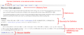
 SEBoK ArticleExplanation.png 2,019 × 1,026; 662 KB
- SEBoK B Purpose for Security.mp4 ; 11.36 MB
- SEBoK C Focus of Security.mp4 ; 24.86 MB
 SEBoK Context Diagram Ifezue Obiako.png 1,123 × 923; 2.09 MB
 SEBoK Context Diagram Inner P1 Ifezue Obiako.png 762 × 774; 1.57 MB
 SEBoK Context Diagram Inner P2 Ifezue Obiako.png 762 × 743; 1.63 MB
 SEBoK Context Diagram Inner P3 Ifezue Obiako.png 762 × 736; 1.73 MB
 SEBoK Context Diagram Inner P4 Ifezue Obiako.png 762 × 767; 1.62 MB
 SEBoK Context Diagram Inner P5 Ifezue Obiako.png 762 × 762; 1.51 MB
 SEBoK Context Diagram Inner P6 Ifezue Obiako.png 762 × 762; 1.61 MB
 SEBoK Context Diagram Inner P7 Ifezue Obiako.png 762 × 762; 1.53 MB
 SEBoK Context Diagram Inner P8 Ifezue Obiako.png 834 × 842; 2.23 MB
- SEBoK D Sec Principles.mp4 ; 64.36 MB
 SEBoK DiscussionExplanation.png 1,947 × 801; 221 KB
- SEBoK E Security Domains.mp4 ; 34.33 MB
- SEBoK F Security Concepts Part 1.mp4 ; 45.79 MB
- SEBoK F Security Concepts Part 2.mp4 ; 103.43 MB
 SEBoK GlossaryExplanation.png 1,918 × 797; 241 KB
- SEBoK Introduction 2021.mp4 ; 99.9 MB
- SEBoK L Sys Think Security.mp4 ; 56.68 MB
- SEBoK N Sec Ops Workflow.mp4 ; 56.84 MB
 SEBoK Navigation Applications.PNG 748 × 569; 43 KB
 SEBoK Navigation Enable.PNG 746 × 568; 42 KB
 SEBoK Navigation Examples.PNG 746 × 570; 41 KB
 SEBoK Navigation Foundation.PNG 746 × 568; 42 KB
 SEBoK Navigation Introduction.PNG 755 × 570; 42 KB
 SEBoK Navigation Management.PNG 743 × 565; 42 KB
 SEBoK Navigation Overview.PNG 652 × 485; 64 KB
 SEBoK Navigation Related.PNG 748 × 569; 42 KB
 SEBoK Navigation Structure.PNG 766 × 574; 59 KB
- SEBoK O1 LDSE Intro.mp4 ; 15.12 MB
- SEBoK O2 ODSE Intro.mp4 ; 13.2 MB
 SEBoK PrimRefExplanation.png 1,647 × 619; 156 KB
 SEBoK SBD Figure5.jpg 775 × 1,018; 108 KB
- SEBoK v2.1.pdf ; 39.4 MB
- SEBoK v2.1 Part1.pdf ; 6.58 MB
- SEBoK v2.1 Part2.pdf ; 8.43 MB
- SEBoK v2.1 Part3.pdf ; 20.26 MB
- SEBoK v2.1 Part4.pdf ; 9.83 MB
- SEBoK v2.1 Part5.pdf ; 6.33 MB
- SEBoK v2.1 Part6.pdf ; 6.9 MB
- SEBoK v2.1 Part7.pdf ; 9.75 MB
- SEBoK v 2.6 20220520.pdf ; 36.79 MB
 SEBoKv05 KA-SpecialtyEng RAM Eqation1.png 209 × 21; 818 bytes
 SEBoKv05 KA-SystDef A simplified meta-data model for system development.png 1,448 × 865; 63 KB
 SEBoKv05 KA-SystDef A simplified ontology for System Definition.png 1,460 × 913; 63 KB
 SEBoKv05 KA-SystDef Assignment Type System Requirement.png 1,177 × 663; 69 KB
 SEBoKv05 KA-SystDef Characteristics of Individual Requirements.png 1,123 × 827; 68 KB
 SEBoKv05 KA-SystDef Characteristics of a set of Requirements.png 1,123 × 521; 45 KB
 SEBoKv05 KA-SystDef Classification Emerging Properties.png 1,208 × 494; 43 KB
 SEBoKv05 KA-SystDef Classification of emergent properties-v2.png 1,208 × 494; 43 KB
 SEBoKv05 KA-SystDef Common Analytical Models.png 1,199 × 824; 79 KB
 SEBoKv05 KA-SystDef Complete Interface Representation.png 1,277 × 416; 17 KB
 SEBoKv05 KA-SystDef Cycle of needs.png 893 × 648; 41 KB
 SEBoKv05 KA-SystDef Example Stakeholder Requirements Classification.png 1,298 × 1,166; 110 KB
 SEBoKv05 KA-SystDef Example Sys Requirements Classification.png 1,306 × 1,214; 118 KB
 SEBoKv05 KA-SystDef Example of states of a requirement.png 408 × 266; 6 KB
 SEBoKv05 KA-SystDef Functional Design relationships.png 968 × 687; 26 KB
 SEBoKv05 KA-SystDef Hierarchical decomposition of a system-of-interest.png 1,150 × 730; 12 KB
 SEBoKv05 KA-SystDef Intellectual creation principles.png 1,193 × 908; 49 KB
 SEBoKv05 KA-SystDef Mapping of technical topics of Know 080711.png 1,504 × 945; 68 KB
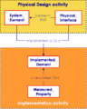
 SEBoKv05 KA-SystDef Physical Design relationships.png 1,238 × 998; 55 KB
 SEBoKv05 KA-SystDef Pitfalls architectural design.png 1,336 × 1,009; 93 KB
 SEBoKv05 KA-SystDef Progressive Approach for Designing.png 1,484 × 779; 62 KB
 SEBoKv05 KA-SystDef Recursion of processes on layers.png 730 × 543; 34 KB
 SEBoKv05 KA-SystDef Recursive instantiation of Definition process.png 1,505 × 1,126; 96 KB
 SEBoKv05 KA-SystDef Requirements and Design in each system block.png 1,339 × 1,020; 66 KB
 SEBoKv05 KA-SystDef Stakeholder Requirements relationships.png 709 × 476; 11 KB
 SEBoKv05 KA-SystDef Stakeholders Identification Based on Life.png 1,013 × 385; 29 KB
 SEBoKv05 KA-SystDef System Analysis relationships.png 1,136 × 946; 46 KB
 SEBoKv05 KA-SystDef System Element Reuse.png 1,087 × 603; 49 KB
 SEBoKv05 KA-SystDef System Requirements relationships.png 709 × 531; 13 KB
 SEBoKv05 KA-SystDef Temporal and decision hierarchy levels.png 1,186 × 779; 37 KB
 SEBoKv05 KA-SystDef Top-down development of design and requirements.png 1,248 × 949; 124 KB
 SEBoKv05 KA-SystDef Types of Costs.png 1,166 × 615; 53 KB
 SEBoKv05 KA-SystDef Types of System Elements and Physical Interfaces.png 1,100 × 348; 25 KB
 SEBoKv05 KA-SystDef ontology elements Functional Design.png 1,172 × 973; 76 KB
 SEBoKv05 KA-SystDef ontology elements Physical Design.png 1,320 × 1,634; 138 KB
 SEBoKv05 KA-SystDef ontology elements System Analysis.png 1,119 × 972; 71 KB
 SEBoKv05 KA-SystDef ontology elements stakeholder requirements.png 1,099 × 1,034; 82 KB
 SEBoKv05 KA-SystDef ontology elements system requirements.png 1,162 × 853; 74 KB
 SEBoKv05 KA-SystDef pitfalls Stakeholder Requirements.png 1,026 × 729; 59 KB
 SEBoKv05 KA-SystDef pitfalls System Analysis.png 1,167 × 366; 25 KB
 SEBoKv05 KA-SystDef pitfalls System Requirements.png 1,119 × 644; 52 KB
 SEBoKv05 KA-SystDef practices Stakeholder Requirements.png 1,024 × 435; 29 KB
 SEBoKv05 KA-SystDef practices System Analysis.png 1,165 × 483; 40 KB
 SEBoKv05 KA-SystDef practices System Requirements.png 1,119 × 973; 72 KB
 SEBoKv05 KA-SystDef practices architectural design.png 1,339 × 629; 56 KB
 SEBoKv05 KA-SystRealiz Definition & performance of V&V Action.png 709 × 759; 25 KB
 SEBoKv05 KA-SystRealiz Implementation relationships.png 573 × 715; 17 KB
 SEBoKv05 KA-SystRealiz Integration Techniques.png 1,335 × 1,228; 122 KB
 SEBoKv05 KA-SystRealiz Integration for PSESystems.png 1,033 × 728; 47 KB
 SEBoKv05 KA-SystRealiz Integration relationships.png 1,239 × 1,016; 46 KB
 SEBoKv05 KA-SystRealiz Synthetic differences between V&V.png 1,107 × 651; 46 KB
 SEBoKv05 KA-SystRealiz V&V Actions lower levels.png 1,122 × 1,109; 73 KB
 SEBoKv05 KA-SystRealiz V&V Actions upper levels.png 1,124 × 1,073; 74 KB
 SEBoKv05 KA-SystRealiz V&V Examples.png 1,164 × 872; 76 KB
 SEBoKv05 KA-SystRealiz V&V Techniques.png 1,178 × 978; 99 KB
 SEBoKv05 KA-SystRealiz V&V per level discussionV2.png 1,486 × 873; 66 KB
 SEBoKv05 KA-SystRealiz V&V relationships.png 1,338 × 807; 38 KB
 SEBoKv05 KA-SystRealiz Verification and Validation level by level.png 1,490 × 775; 48 KB
 SEBoKv05 KA-SystRealiz Verification and Validation level per level V4.png 1,487 × 891; 74 KB
 SEBoKv05 KA-SystRealiz ontology V&V.png 1,127 × 889; 65 KB
 SEBoKv05 KA-SystRealiz ontology within System Integration.png 1,127 × 666; 49 KB
 SEBoKv05 KA-SystRealiz ontology within implementation.png 1,123 × 548; 45 KB
 SEBoKv05 KA-SystRealiz pitfalls with System Integration.png 1,127 × 298; 22 KB
 SEBoKv05 KA-SystRealiz pitfalls with V&V.png 1,127 × 381; 30 KB
 SEBoKv05 KA-SystRealiz practices with System Integration.png 1,127 × 576; 47 KB
 SEBoKv05 KA-SystRealiz practices with V&V.png 1,224 × 1,033; 99 KB
 SEBoKv05 KA-SystRealiz simplified view of a meta-data model.png 1,424 × 860; 57 KB
 SEBoKv075 KA-SystDef A simplified ontology for System Definition.png 1,130 × 785; 228 KB
 SEBoKv075 KA-SystDef Complete Interface Representation.png 1,275 × 415; 48 KB
 SEBoKv075 KA-SystDef Encapsulation.png 1,464 × 573; 104 KB
 SEBoKv075 KA-SystDef Limited nb in decomposition.png 1,349 × 804; 114 KB
 SEBoKv075 KA-SystDef Pitfalls Logical Design.png 1,035 × 725; 168 KB
 SEBoKv075 KA-SystDef Pitfalls Physical Design.png 1,328 × 676; 193 KB
 SEBoKv075 KA-SystDef Practices Logical Design.png 1,036 × 481; 120 KB


_Concept_maps_additions_hgs_15_Aug.png)


