Stakeholder Requirements Definition
The System requirements are all of the requirements at the “system level” that have been properly translated from the list of stakeholders' requirements. The System Requirements form the basis of system design, verification, and stakeholder acceptance.
System Requirements play major roles in the engineering activities. They serve:
- as the essential inputs of the system design activities.
- as reference for the system validation activities.
- as a communication means, between the various technical staff that interact within the project.
Principles Governing System Requirements
Origin in Stakeholder Requirements
The set of Stakeholder Requirements may contain vague, ambiguous, and qualitative “user-oriented” need statements that are difficult to use for design or to verify. Each of these requirements may need to be further clarified and translated into “engineering-oriented” language to enable proper design and verification activities. The System Requirements resulting from this translation are expressed in technical language useful for design; unambiguous, consistent, coherent, exhaustive, and verifiable. Of course, close coordination with the stakeholders is necessary to ensure the translation is accurate.
As an example, a need or an expectation such as "To easily maneuver a car to park it," will be transformed in a set of Stakeholder Requirements such as, "Increase the drivability of the car", "Decrease the effort for handling", "Assist the piloting", "Protect the coachwork against shocks or scratch", etc. Translating, for example, the Stakeholder Requirement "Increase the drivability of the car", results in a set of System Requirements specifying measurable characteristics such as the turning circle (steering lock), the wheelbase, etc.
Traceability and assignment of System Requirements during design
Requirements traceability provides the ability to trace information from the origin of the Stakeholder Requirements at the top level to the lowest level of the system hierarchy - see section "Top-down and recursive approach to system decomposition" in the System Definition article. Traceability is also used to provide an understanding of the extent of a change as an input to impact analyses conducted with respect to proposed engineering improvements or requests for change.
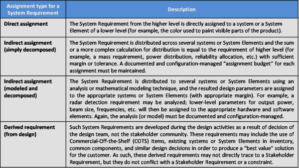
During design, the assignment of requirements from one level to lower levels in the system hierarchy can be accomplished using several methods, as appropriate - see Table 1.
Classification of System Requirements
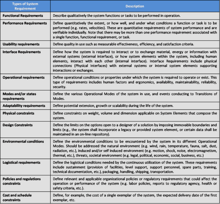
Several classifications of System Requirements are possible, depending on the requirements definition methods and/or the design methods used. (ISO/IEC. 2011) provides a classification summarized below – see references for other interesting classifications. An example is given in Table 2.
Process Approach – System Requirements
Purpose and Principle of the Approach
The purpose of the system requirements analysis process is to transform the stakeholder, user-oriented view of desired services and properties into a technical view of the product that meets the operational needs of the user. This process builds a representation of the system that will meet Stakeholder Requirements and that, as far as constraints permit, does not imply any specific implementation. It results in measurable System Requirements that specify, from the supplier’s perspective, what performance and non-performance characteristics it must possess in order to satisfy stakeholders' requirements. (ISO/IEC. 2008)
Activities of the process
Major activities and tasks performed during this process include:
- Analyze the Stakeholder Requirements to check completeness of expected services and operational scenarios , conditions, Operational Modes, and constraints.
- Define the System Requirements and its rationale .
- Classify the System Requirements using suggested classifications – see examples above.
- Incorporate the derived requirements (coming from design) into the System Requirements baseline.
- Establish the upward traceability with the Stakeholder Requirements.
- Verify the quality and completeness of each System Requirement and the consistency of the set of System Requirements.
- Validate the content and relevance of each System Requirement against the set of Stakeholder Requirements.
- Identify potential risks (or threats and hazards) that could be generated by the System Requirements.
- Synthesize, record, and manage the System Requirements and potential associated Risks.
Artifacts and Ontology Elements
This process may create several artifacts such as:
- System Requirements Document
- System Requirements Justification Document (for traceability purpose)
- System Requirements Database, including traceability, analysis, rationale, decisions, and attributes, where appropriate.
- System External Interface Requirements Document (this document describes the interfaces of the system with external elements of its context of use; the interface requirements can be integrated or not to the System Requirements Document above).
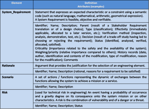
This process handles the ontology elements of Table 3.
Checking and Correctness of System Requirements
System Requirements should be checked to gauge whether they are well expressed and appropriate. There are number of characteristics which can be used to check System Requirements. The set of System Requirements can be verified using standard peer review techniques and by comparing each requirement against the set of requirements characteristics listed in Table 2 and Table 3 of section "Presentation and Quality of Requirements".
The requirements can be further validated using the requirements elicitation and rationale capture described in section "Methods and Modeling Techniques."
Methods and Modeling Techniques
Requirements Elicitation and Prototyping
Requirements Elicitation requires user involvement, and can be effective in gaining stakeholder involvement and buy-in. QFD (Quality Function Deployment) and prototyping are two common techniques that can be applied and are defined in this section. In addition, interviews, focus groups, and Delphi techniques are often applied to elicit requirements.
QFD is a powerful technique to elicit requirements and compare design characteristics against user needs (Hauser and Clausing, 1988). The inputs to the QFD application are user needs and operational concepts, so it is essential that the users participate. Users from across the life cycle should be included so that all aspects of user needs are accounted for and prioritized.
Early prototyping can help the users and developers interactively identify functional and operational requirements and user interface constraints. The prototyping allows for realistic user interaction, discovery, and feedback, as well as some sensitivity analysis. This improves the user's understanding of the requirements and increases the probability of satisfying their actual needs.
Capturing Requirements Rationale
One powerful and cost-effective technique to translate Stakeholder Requirements to System Requirements is to capture the rationale for each requirement. Requirements rationale is merely a statement as to why the requirement exists, any assumptions made, the results of related design studies, or any other related supporting information. This supports further requirements analysis and decomposition. The rationale can be captured directly in the requirements database. (Hull, M. E. C., Jackson, K., Dick, A. J. J. 2010).
Some of the benefits include:
- Reducing the total number of requirements. The process aids in identifying duplicates. Reducing requirements count will reduce project cost and risk.
- Early exposure of bad assumptions.
- Removes design implementation. Many poorly written stakeholder requirements are design requirements in disguise, in that the customer is intentionally or unintentionally specifying a candidate implementation.
- Improves communication with the stakeholder community. By capturing the requirements rationale for all Stakeholders Requirements, the line of communication between the users and the designers is greatly improved. Adapted from (Hooks, I. F., and K. A. Farry. 2000) Chapter 8.
Modeling Techniques
Modeling techniques that can be used when requirements must be detailed or refined, or when they address topics not considered during the Stakeholder Requirements Definition and Mission Analysis include:
- State-charts models (ISO/IEC. 2011) Section 8.4.2
- Scenarios modeling (ISO/IEC. 2011) Section 6.2.3.1
- Simulations, prototyping (ISO/IEC. 2011) Section 6.3.3.2
- Quality Function Deployment (INCOSE. 2010) p. 83
- Sequence diagram, Activity diagram, Use case, State machine diagram, Requirements diagram of SysML
- Functional Flow Block Diagram for Operational Scenario
Presentation and Quality of Requirements
Generally, requirements are provided in a textual form. Guidelines exist for writing good requirements; they include recommendations about syntax of requirements statements, wording (exclusions, representation of concepts, etc.), characteristics(specific, measurable, achievable, feasible, testable, etc.). Refer to (INCOSE. 2010) section 4.2.2.2 and (ISO/IEC. 2011).
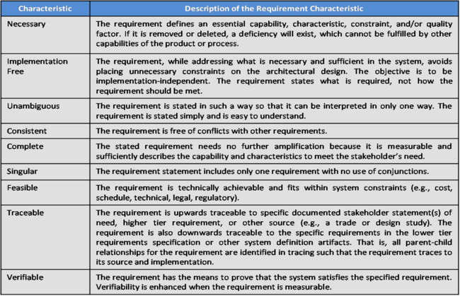
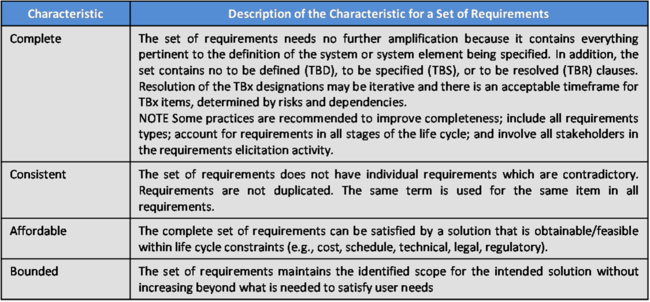
There are several characteristics of requirements and sets of requirements that ensure the quality of requirements. These are used both to aid the development of the requirements and to verify the implementation of requirements into the solution. Table 4 provides a list and descriptions of the characteristics for individual requirements and Table 5 provides a list and descriptions of characteristics for a set of requirements, as adapted from (ISO/IEC. 2011) sections 5.2.5 and 5.2.6.
Requirements in Tables
Requirements may be provided in a table, especially when specifying a set of parameters for the system or a system element. It is good practice to make standard table templates available. For tables, the following conventions apply:
- Invoke each requirements table in the requirements set that clearly points to the table.
- Identify each table with a unique title and table number.
- Include the word “requirements” in the table title.
- Identify the purpose of the table in the text immediately preceding it and include an explanation of how to read and use the table, including context and units.
- For independent-dependant variable situations, organize the table in a way that best accommodates the use of the information.
- Each cell should contain, at most, a single requirement.
Requirements in Flow Charts
Flow charts often contain requirements in a graphical form. These requirements may include logic that must be incorporated into the system, operational requirements, process or procedural requirements, or other situations that are best defined graphically by a sequence of interrelated steps. For flow charts, the following conventions apply:
- Invoke flow charts in the requirements set that clearly points to the flow chart.
- Identify each flow chart with a unique title and figure number.
- Include the word “requirements” in the title of the flow chart
- Clearly indicate and explain unique symbols that represent requirements in the flow chart.
Requirements in Drawings
Drawings also provide a graphical means to define requirements. The type of requirement defined in a drawing depends on the type of drawing. Following conventions apply:
- Drawings are used when they can aid in the description of the following:
- Spatial requirements
- Interface requirements
- Layout requirements
- Invoke drawings in the requirements set that clearly points to the drawing.
Practical Considerations about System Requirements
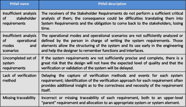
There are several pitfalls that will inhibit the generation and management of an optimal set of System Requirements. See Table 6.
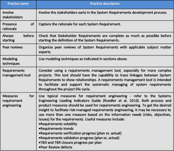
The following proven practices in system requirements engineering have repeatedly been shown to reduce project risk and cost, foster customer satisfaction, and produce successful system development. See Table 7.
References
Works Cited
Hauser, J. and D. Clausing. 1988. "The House of Quality." Harvard Business Review. (May - June 1988).
Hooks, I. F., and K. A. Farry. 2000. Customer-centered products: Creating successful products through smart requirements management. New York, NY, USA: American Management Association.
Hull, M. E. C., Jackson, K., Dick, A. J. J. 2010. Systems Engineering. 3rd ed. London, UK: Springer.
INCOSE. 2011. Systems Engineering Handbook: A Guide for System Life Cycle Processes and Activities Version 3.2.1. San Diego, CA, USA: International Council on Systems Engineering (INCOSE), INCOSE-TP-2003-002-03.2.1.
ISO/IEC/IEEE. 2011. Systems and Software Engineering - Requirements Engineering. Geneva, Switzerland: International Organization for Standardization (ISO)/International Electrotechnical Commission/ Institute of Electrical and Electronics Engineers (IEEE), (IEC), ISO/IEC/IEEE 29148.
ISO/IEC/IEEE. 2008. Systems and Software Engineering - System Life Cycle Processes. Geneva, Switzerland: International Organization for Standardization (ISO)/International Electronical Commission (IEC), Institute of Electrical and Electronics Engineers. ISO/IEC/IEEE 15288:2008 (E).
Primary References
ISO/IEC/IEEE. 2011. Systems and Software Engineering - Requirements Engineering. Geneva, Switzerland: International Organization for Standardization (ISO)/International Electrotechnical Commission/ Institute of Electrical and Electronics Engineers (IEEE), (IEC), ISO/IEC/IEEE 29148.
ISO/IEC/IEEE. 2008. Systems and Software Engineering - System Life Cycle Processes. Geneva, Switzerland: International Organization for Standardization (ISO)/International Electronical Commission (IEC), Institute of Electrical and Electronics Engineers. ISO/IEC/IEEE 15288:2008 (E).
INCOSE. 2011. INCOSE Systems Engineering Handbook: A Guide for System Life Cycle Processes and Activities. Version 3.2.1. San Diego, CA, USA: International Council on Systems Engineering (INCOSE), INCOSE-TP-2003-002-03.2.1.
Lamsweerde, A. van. 2009. Requirements Engineering. New York, NY, USA: Wiley.
Additional References
Faisandier, A. 2011 (unpublished). Engineering and Architecting Multidisciplinary Systems.
Hooks, I.F., and K.A. Farry. 2000. Customer-Centered Products: Creating Successful Products through Smart Requirements Management. New York, NY, USA: American Management Association.
Hull, M.E.C., K. Jackson, A.J.J. Dick. 2010. Systems Engineering. 3rd ed. London, UK: Springer.
Roedler, G., D. Rhodes, C. Jones, and H. Schimmoller. 2010. Systems Engineering Leading Indicators Guide. Version 2.0. San Diego, CA, USA: International Council on Systems Engineering (INCOSE), INCOSE-TP-2005-001-03.
SEBoK Discussion
Please provide your comments and feedback on the SEBoK below. You will need to log in to DISQUS using an existing account (e.g. Yahoo, Google, Facebook, Twitter, etc.) or create a DISQUS account. Simply type your comment in the text field below and DISQUS will guide you through the login or registration steps. Feedback will be archived and used for future updates to the SEBoK. If you provided a comment that is no longer listed, that comment has been adjudicated. You can view adjudication for comments submitted prior to SEBoK v. 1.0 at SEBoK Review and Adjudication. Later comments are addressed and changes are summarized in the Letter from the Editor and Acknowledgements and Release History.
If you would like to provide edits on this article, recommend new content, or make comments on the SEBoK as a whole, please see the SEBoK Sandbox.
blog comments powered by Disqus