Difference between revisions of "Systems Engineering and Management"
Tag: visualeditor |
Tag: visualeditor |
||
| Line 40: | Line 40: | ||
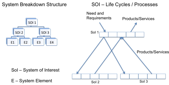
On the left side of Figure 1, there are three [[System-of-Interest (glossary)|SoI's]] identified in the formation of a [[System Breakdown Structure (glossary) |system breakdown structure]]. SoI 1 is broken down into its basic elements, which in this case are systems as well (SoI 2 and SoI 3). These two systems are composed of [[System Element (glossary)|system elements]] that are not refined any further. | On the left side of Figure 1, there are three [[System-of-Interest (glossary)|SoI's]] identified in the formation of a [[System Breakdown Structure (glossary) |system breakdown structure]]. SoI 1 is broken down into its basic elements, which in this case are systems as well (SoI 2 and SoI 3). These two systems are composed of [[System Element (glossary)|system elements]] that are not refined any further. | ||
| − | On the right side of Figure 1, each SoI has a corresponding [[Life Cycle Model (glossary)|life cycle model (glossary)]] which is composed of the stages that are populated with processes. The function of these processes is to define the work that is to be performed. Note that some of the requirements defined to meet the need are distributed in the early stages of the life cycle for SoI 1, while others are designated to the life cycles of SoI 2 or SoI 3. The decomposition of the system illustrates the fundamental concept of [[Recursion (glossary)|recursion (glossary)]] as defined in the ISO/IEC 15288 standard; with the standard being reapplied for each SoI (ISO/IEC 15288). It is important to point out that the stakeholder requirements may be allocated to different system elements, which may be integrated in different life cycle stages of any of the three SoI's; however, together they form a cohesive system. For example, SoI 1 may be an embedded system composed of a hardware system, SoI 2 composed of a chassis and a motor, and Sol 3 a [[Software System (glossary)|software system]]. | + | On the right side of Figure 1, each SoI has a corresponding [[Life Cycle Model (glossary)|life cycle model (glossary)]] which is composed of the stages that are populated with processes. The function of these processes is to define the work that is to be performed. Note that some of the requirements defined to meet the need are distributed in the early stages of the life cycle for SoI 1, while others are designated to the life cycles of SoI 2 or SoI 3. The decomposition of the system illustrates the fundamental concept of [[Recursion (glossary)|recursion (glossary)]] as defined in the ISO/IEC/IEEE 15288 standard; with the standard being reapplied for each SoI (ISO/IEC/IEEE 15288 2015). It is important to point out that the stakeholder requirements may be allocated to different system elements, which may be integrated in different life cycle stages of any of the three SoI's; however, together they form a cohesive system. For example, SoI 1 may be an embedded system composed of a hardware system, SoI 2 composed of a chassis and a motor, and Sol 3 a [[Software System (glossary)|software system]]. |
When performing SE processes in stages, [[Iteration (glossary)|iteration (glossary)]] between stages is often required (e.g. in successive refinement of the definition of the system or in providing an update or upgrade of an existing system). The work performed in the processes and stages can be performed in a [[Concurrent (glossary)|concurrent]] manner within the life cycle of any of the systems of interest and also among the multiple life cycles. | When performing SE processes in stages, [[Iteration (glossary)|iteration (glossary)]] between stages is often required (e.g. in successive refinement of the definition of the system or in providing an update or upgrade of an existing system). The work performed in the processes and stages can be performed in a [[Concurrent (glossary)|concurrent]] manner within the life cycle of any of the systems of interest and also among the multiple life cycles. | ||
Revision as of 09:23, 13 May 2015
This part of the SEBoK focuses on the general knowledge of how systems are engineered. It builds upon Part 2, which discusses the what element of systems. Part 3 provides a basis for the engineering of product systems, service systems, enterprise systems, and systems of systems (SoS), as described in Part 4. Part 3 defines systems engineering; provides an overview of the common uses of life cycle models in systems engineering (SE); discusses the most commonly-used SE processes; provides additional references to the common methods, tools, and techniques used in these processes; and discusses the management aspects of SE.
Part 3 provides only an overview of how systems are engineered in a generic sense. Part 4 provides more specific information as to how the principles discussed in Part 3 are applied differently in consideration of the type of system that is being engineered (e.g. product, service, enterprise, or system of systems (SoS)). Part 5 explains how an organization may approach utilizing these principles in a holistic manner. Part 6 contains references to other related disciplines, which may be utilized in the various SE processes described in Part 3, but do not fall under the umbrella of SE.
Knowledge Areas in Part 3
Each part of the SEBoK is divided into knowledge areas (KAs), which are groupings of information with a related theme. Part 3 contains the following knowledge areas:
- Life Cycle Models
- Concept Definition
- System Definition
- System Realization
- System Deployment and Use
- Systems Engineering Management
- Product and Service Life Management
- Systems Engineering Standards
See the article Matrix of Implementation Examples for a mapping of case studies and vignettes included in Part 7 to topics covered in Part 3.
Systems Engineering Definition
There is no community consensus on a single definition for "systems engineering"; the term has different connotations in different domains. However, one of the more commonly recognized definitions in the field is that of the International Council on Systems Engineering (INCOSE) (see http://www.incose.org):
An interdisciplinary approach and means to enable the realization of successful systems. It focuses on defining customer needs and required functionality early in the development cycle, documenting requirements, then proceeding with design synthesis and system validation while considering the complete problem:
- Operations
- Performance
- Test
- Manufacturing
- Cost & Schedule
- Training & Support
- Disposal
Systems engineering integrates all the disciplines and specialty groups into a team effort forming a structured development process that proceeds from concept to production to operation. Systems engineering considers both the business and the technical needs of all customers with the goal of providing a quality product that meets the user needs. (INCOSE 2012)
This is the definition that is frequently referenced throughout the SEBoK. SE is also the application of engineering practices and holistic systems thinking that works in combination with domain engineering, human sciences, management, and commercial disciplines in order to support the engineering of one or more systems-of-interest (SoI). SE may also be considered an interdisciplinary approach, governing the complete technical and managerial effort that is required to transform a set of customer needs, expectations, and constraints into a solution and to continue to support that solution throughout its life cycle. Each of these perspectives is valuable for gaining a holistic view of SE.
Generic Systems Engineering Paradigm
Figure 1 identifies the overall goals of any SE effort, which are: the understanding of stakeholder value; the selection of a specific need to be addressed; the transformation of that need into a system (the product or service that provides for the need); and the use of that product or service to provide the stakeholder value. This paradigm has been developed according to the principles of the systems approach discussed in Part 2 and is used to establish a basis for the KAs in Part 3 and Part 4 of the SEBoK.
On the left side of Figure 1, there are three SoI's identified in the formation of a system breakdown structure. SoI 1 is broken down into its basic elements, which in this case are systems as well (SoI 2 and SoI 3). These two systems are composed of system elements that are not refined any further.
On the right side of Figure 1, each SoI has a corresponding life cycle model which is composed of the stages that are populated with processes. The function of these processes is to define the work that is to be performed. Note that some of the requirements defined to meet the need are distributed in the early stages of the life cycle for SoI 1, while others are designated to the life cycles of SoI 2 or SoI 3. The decomposition of the system illustrates the fundamental concept of recursion as defined in the ISO/IEC/IEEE 15288 standard; with the standard being reapplied for each SoI (ISO/IEC/IEEE 15288 2015). It is important to point out that the stakeholder requirements may be allocated to different system elements, which may be integrated in different life cycle stages of any of the three SoI's; however, together they form a cohesive system. For example, SoI 1 may be an embedded system composed of a hardware system, SoI 2 composed of a chassis and a motor, and Sol 3 a software system.
When performing SE processes in stages, iteration between stages is often required (e.g. in successive refinement of the definition of the system or in providing an update or upgrade of an existing system). The work performed in the processes and stages can be performed in a concurrent manner within the life cycle of any of the systems of interest and also among the multiple life cycles.
This paradigm provides a fundamental framework for understanding generic SE (seen in Part 3), as well as for the application of SE to the various types of systems described in Part 4.
Applying Iteration and Recursion to Systems Engineering in the Life Cycle
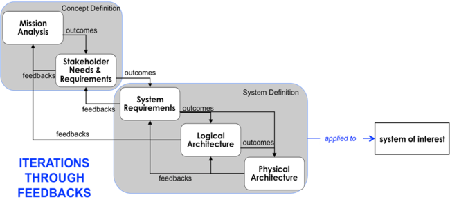
The concept of iteration is also applied to processes. Figure 2 below gives an example of iteration in life cycle processes. The processes in this example are further discussed in the System Definition KA.
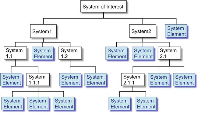
The comprehensive definition of a SoI is generally achieved using decomposition layers and system elements . Figure 3 presents a fundamental schema of a system breakdown structure.
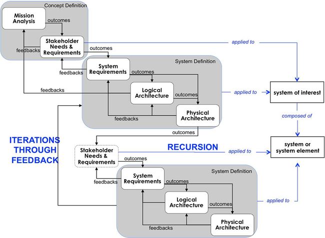
In each decomposition layer and for each system, the System Definition processes are applied recursively because the notion of "system" is in itself recursive; the notions of SoI, system, and system element are based on the same concepts (see Part 2). Figure 4 shows an example of the recursion of life cycle processes.
Value of Ontology Concepts for Systems Engineering
Ontology is the set of entities presupposed by a theory (Collins English Dictionary 2011). Systems engineering, and system development in particular, is based on concepts related to mathematics and proven practices. A SE ontology can be defined considering the following path.
SE provides engineers with an approach based on a set of concepts (i.e., stakeholder, requirement, function, scenario, system element, etc.) and generic processes. Each process is composed of a set of activities and tasks gathered logically around a theme or a purpose. A process describes “what to do” using the applied concepts. The implementation of the activities and tasks is supported by methods and modeling techniques, which are composed themselves of elementary tasks; they describe the “how to do” of SE. The activities and tasks of SE are transformations of generic data using predefined concepts. Those generic data are called entities, classes, or types. Each entity is characterized by specific attributes, and each attribute may have a different value. All along their execution, the activities and tasks of processes, methods, and modeling techniques exchange instances of generic entities according to logical relationships. These relationships allow the engineer to link the entities between themselves (traceability) and to follow a logical sequence of the activities and the global progression (engineering management). Cardinality is associated with every relationship, expressing the minimum and maximum number of entities that are required in order to make the relationship valid. Additional information on this subject may be found in Engineering Complex Systems with Models and Objects (Oliver, Kelliher, and Keegan 1997).
The set of SE entities and their relationships form an ontology, which is also referred to as an "engineering meta-model". Such an approach is used and defined in the ISO 10303 standard (ISO 2007). There are many benefits to using an ontology. The ontology allows or forces:
- the use of a standardized vocabulary, with carefully chosen names, which helps to avoid the use of synonyms in the processes, methods, and modeling techniques
- the reconciliation of the vocabulary used in different modeling techniques and methods
- the automatic appearance of the traceability requirements when implemented in databases, SE tools or workbenches, and the quick identification of the impacts of modifications in the engineering data set
- the continual observation of the consistency and completeness of engineering data; etc.
Throughout Part 3, there are discussions of the ontological elements specifically relevant to a given topic.
Terminology: Process, Architecture and Requirement
There are terms with multiple definitions used in Part 3 and the rest of the SEBoK. Understanding how and where they are used is important. This section discusses them from a variety of contexts to minimize confusion.
The terms process, architecture, and requirement are fundamental to topics within SE; below, they are defined in general, partially elaborated upon, and outlined as to how they are used in different parts of SEBoK for further reference.
Process
A process is a series of actions or steps taken in order to achieve a particular end; as a verb it is the performing of the operations. Processes can be performed by humans or machines transforming inputs into outputs.
In SEBoK processes are interpreted in several ways, including: technical, lifecycle, business, or manufacturing flow processes. Many of the Part 3 sections are structured along technical processes (e.g. design, verification); however, Life Cycle Models applies the concept at the high level of a program lifecycle sequence (e.g. rational unified process (RUP), Vee model, etc.).
Part 4: Applications of Systems Engineering and Part 5: Enabling Systems Engineering utilize processes that are related to services and business enterprise operations. See process for various interpretations of this term.
Architecture
An architecture refers to the the organizational structure of a system, whereby the system can be defined in different contexts. Architecting is the art or practice of designing the structures.
Architectures can apply for a system, product, enterprise, or service. For example, Part 3 mostly considers product-related architectures that systems engineers create, but enterprise architecture describes the structure of an organization. Part 5: Enabling Systems Engineering interprets enterprise architecture in a much broader manner than an IT system used across an organization, which is a specific instance of architecture. More complete definitions are available architecture .
Frameworks are closely related to architectures, as they are ways of representing architectures. The terms Architecture Framework and Architectural Framework both refer to the same. Examples include: DoDAF, MoDAF, NAF for representing systems in defense applications, the TOGAF open group Architecture Framework, and the Federal Enterprise Architecture Framework (FEAF) for information technology acquisition, use and disposal. See the glossary of terms Architecture Framework for definition and other examples.
Requirement
A requirement is something that is needed or wanted, but may not be compulsory in all circumstances. Requirements may refer to product or process characteristics or constraints. Different understandings of requirements are dependent on process state, level of abstraction, and type (e.g. functional, performance, constraint). An individual requirement may also have multiple interpretations over time.
Requirements exist at multiple levels of enterprise or system with multiple levels abstraction. This ranges from the highest level of the enterprise capability or customer need to the lowest level of the system design. During the Concept Definition, as the enterprise identifies new capabilities that are desired, the business or mission analysis develops a high level set of mission requirements that reflect the problem space perspective. As the solution space is explored and solution classes are characterized, stakeholder needs are developed and transformed into stakeholder requirements (user perspective). After the solution class has been determined and the specific solution is sought, during the System Definition the stakeholder requirements are transformed into system requirements (solution perspective). As the system definition recursively defines the lower level detail of the solution, requirements are defined with lower level of abstraction. At the highest level, the ideal requirement is implementation-independent, and therefore not specific to a solution, allowing for a range of possible solutions. At the lowest level, requirement statements may become more specific to the selected solution. Thus, requirements need to be defined at the appropriate level of detail for the level of the entity to which it applies. See the article Process Synopsis for further detail on the transformation of needs and requirements from the enterprise to the lowest system element.
Concept Definition has further descriptions of business or enterprise and stakeholder needs and requirements. It discusses how the new capability for the business or enterprise is defined as part of the understanding of the problem space. It also discusses the development of the stakeholder needs and their transformation into requirements from the user perspective.
System Definition has further descriptions of requirements and their types (e.g. system requirement, stakeholder requirement, derived requirement). It discusses how different process roles/ states, levels, and the nature of requirements apply to the understanding of requirements. Also see requirement.
Furthermore, these terms are intertwined and linked to additional concepts. For example, processes are used to generate architectures and requirements. Processes are also architectures themselves, since the activities form a structure with connections between them. There are process and architecture requirements, with the requirement depending on the process state. These are some of the ways that these terms and concepts tie together in systems engineering.
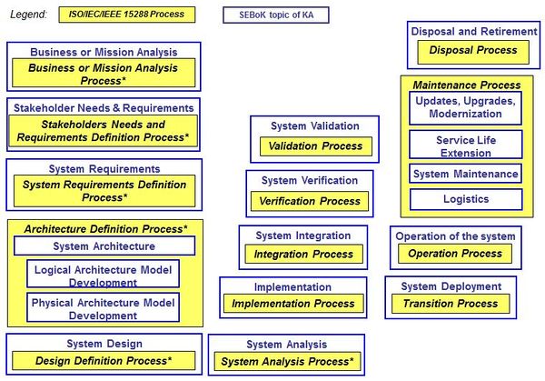
Mapping of Topics to ISO/IEC 15288, System Life Cycle Processes
Figure 5, below, shows the relative position of the KA's of the SEBoK with respect to the processes outlined in the ISO/IEC/IEEE 15288 (ISO/IEC/IEEE 15288 2015) standard. As shown, all of the major processes described in ISO/IEC 15288 are discussed within the SEBoK, though the organization of topics may differ.
References
Works Cited
Collins English Dictionary, s.v. "Ontology." 2011.
Faisandier, A. 2012. Systems Architecture and Design. Belberaud, France: Sinergy'Com.
INCOSE. 2012. Systems Engineering Handbook: A Guide for System Life Cycle Processes and Activities, version 3.2.2. San Diego, CA, USA: International Council on Systems Engineering (INCOSE), INCOSE-TP-2003-002-03.2.2.
ISO/IEC. 2003. Systems Engineering — A Guide for The Application of ISO/IEC 15288 System Life Cycle Processes. Geneva, Switzerland: International Organization for Standardization (ISO)/International Electrotechnical Commission (IEC), ISO/IEC 19760:2003 (E).
ISO/IEC/IEEE. 2015. Systems and Software Engineering -- System Life Cycle Processes. Geneva, Switzerland: International Organisation for Standardisation / International Electrotechnical Commissions / Institute for Electrical and Electronics Engineers. ISO/IEC/IEEE 15288:2015.
ISO. 2007. Systems Engineering and Design. Geneva, Switzerland: International Organization for Standardization (ISO). ISO 10303-AP233.
Oliver, D., T. Kelliher, and J. Keegan. 1997. Engineering Complex Systems with Models and Objects. New York, NY, USA: McGraw-Hill.
Primary References
INCOSE. 2012. Systems Engineering Handbook: A Guide for System Life Cycle Processes and Activities, version 3.2.2. San Diego, CA, USA: International Council on Systems Engineering (INCOSE), INCOSE-TP-2003-002-03.2.2.
ISO/IEC/IEEE. 2015. Systems and Software Engineering -- System Life Cycle Processes. Geneva, Switzerland: International Organisation for Standardisation / International Electrotechnical Commissions. ISO/IEC/IEEE 15288:2015.
Additional References
Bell Telephone Laboratories. 1982. Engineering and Operations in the Bell System. Murray Hill, NJ: Bell Telephone Laboratories.
Fortescue, P.W., J. Stark, and G. Swinerd. 2003. Spacecraft Systems Engineering. New York, NY, USA: J. Wiley.
SEBoK Discussion
Please provide your comments and feedback on the SEBoK below. You will need to log in to DISQUS using an existing account (e.g. Yahoo, Google, Facebook, Twitter, etc.) or create a DISQUS account. Simply type your comment in the text field below and DISQUS will guide you through the login or registration steps. Feedback will be archived and used for future updates to the SEBoK. If you provided a comment that is no longer listed, that comment has been adjudicated. You can view adjudication for comments submitted prior to SEBoK v. 1.0 at SEBoK Review and Adjudication. Later comments are addressed and changes are summarized in the Letter from the Editor and Acknowledgements and Release History.
If you would like to provide edits on this article, recommend new content, or make comments on the SEBoK as a whole, please see the SEBoK Sandbox.
blog comments powered by Disqus