Incremental Life Cycle Model
This article discusses incremental and evolutionary development models beyond variants of the System Life Cycle Process Models: Vee.
Incremental and Evolutionary Development
Overview of the Incremental Approach
Incremental and iterative development (IID) methods have been in use since the 1960s (and perhaps earlier). They allow a project to provide an initial capability followed by successive deliveries to reach the desired System of Interest.
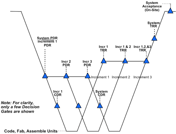
The IID approach, shown in Figure 1, is used when:
- rapid exploration and implementation of part of the system is desired;
- the requirements are unclear from the beginning;
- funding is constrained;
- the customer wishes to hold the System-of-Interest open to the possibilities of inserting new technology at a later time; and
- experimentation is required to develop successive prototype versions.
The features that distinguish IID from the single-pass, plan-driven approach are velocity and adaptability.
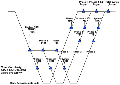
Incremental development may also be “plan-driven” in nature when the requirements are known early in the life cycle. The development of the functionality is performed incrementally to allow for the latest technology insertion or potential changes in needs or requirements.
Incremental development also imposes constraints. The model shown in Figure 2 uses the increments to develop high-risk subsystems (or components) early, but the system cannot function until all increments are complete.
Overview of the Evolutionary Approach
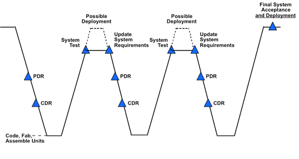
A specific IID methodology called evolutionary development is common in research and development environments. Figure 3 illustrates this approach. It was used in the evolution of the high temperature tiles for the NASA Space Shuttle (Forsberg 1995).
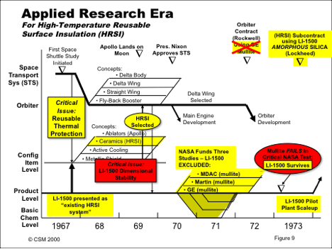
The real world development environment is complex to map because many different project cycles are underway simultaneously. Figure 4 shows the applied research era for the development of the space shuttle orbiter and illustrates multi-levels of simultaneous development, trade studies, and ultimately implementation.
Iterative Software Development Process Models
Software is a flexible and malleable medium which facilitates iterative analysis, design, construction, verification, and validation to a greater degree than is usually possible for the physical components of a system. Each iteration of an iterative development model adds code to the growing software base; the expanded code base is tested, reworked as necessary, and demonstrated to satisfy the requirements for that baseline.
Process models for software development support iterative development on cycles of various lengths. Table 1 lists three iterative software development models presented in the Life Cycle Models topic area and the aspects of software development that are emphasized by those models.
Iterative-Development Process Models
Developing and modifying software involves creative processes that are subject to many external and changeable forces. Long experience has shown that it is impossible to “get it right” the first time, and that iterative development processes are preferable to linear, sequential development process models, such as the well-known Waterfall model.
In iterative development, each cycle of the iteration subsumes the software of the previous iteration and adds new capabilities to the evolving product to produce an expanded version of the software. Iterative development processes provide the following advantages:
- continuous integration, verification, and validation of the evolving product;
- frequent demonstrations of progress;
- early detection of defects;
- early warning of process problems;
- systematic incorporation of the inevitable rework that occurs in software development; and
- early delivery of subset capabilities (if desired).
Iterative development takes many forms in software engineering, including these:
- An Incremental-build process is used to produce periodic (typically weekly) builds of increasing product capabilities.
- Agile development is used to closely involve a prototypical customer in an iterative process that may repeat on a daily basis.
- The Spiral model is used to confront and mitigate risk factors encountered in developing the successive versions of a product.
The Incremental-Build Model
The Incremental-build model is a build-test-demonstrate model of iterative cycles in which frequent demonstrations of progress, verification, and validation of work-to-date are emphasized. The model is based on stable requirements and a software architectural specification. Each build adds new capabilities to the incrementally growing product. The process ends when the final version is verified, validated, demonstrated, and accepted by the customer.
Table 2 lists some partitioning criteria for incremental development into incremental build units of, typically, one calendar-week each. The increments and the number of developers available to work on the project determine the number of features that can be included in each incremental build. This, in turn, determines the overall schedule.
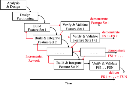
Figure 5 illustrates the details of the build-verify-validate-demonstrate cycles in the Incremental-build process. Each build includes detailed design, coding, integration, review, and testing done by the developers. In cases where code is to be reused without modification, some or all of an incremental build may consist of review, integration, and testing of the base code augmented with the reused code.
Development of an increment may result in reworking previous components developed for integration to fix defects.
Incremental verification, validation, and demonstration, as illustrated in Figure 5, overcomes two of the major problems of a Waterfall approach: 1) problems are exposed early and can be corrected as they occur; and 2) minor in-scope changes to requirements that occur as a result of incremental demonstrations can be incorporated in subsequent incremental builds.
Figure 5 also illustrates that it may be possible to overlap successive builds of the product. It may be possible, for example, to start a detailed design of the next version while the present version is being validated.
Three factors determine the degree of overlap that can be achieved:
- availability of personnel;
- adequate progress on the previous version; and
- the risk of significant rework on the next overlapped build because of changes to the previous in-progress build.
The Incremental-build process works well when each team consists of 2 to 5 developers, plus a team leader (who is also a technical contributor), but can be scaled up for larger projects.
A significant advantage of an Incremental-build process is that features built first are verified, validated, and demonstrated most frequently because subsequent builds incorporate the features of the earlier builds. In building the software to control a nuclear reactor, for example, the emergency shutdown software could be built first. Operation of emergency shutdown (scramming) would then be verified and validated in conjunction with the features of each successive build.
In summary, the Incremental-build model, like all iterative models, provides the advantages of continuous integration and validation of the evolving product, frequent demonstrations of progress, early warning of problems, early delivery of subset capabilities, and systematic incorporation of the inevitable rework that occurs in software development.
The Role of Prototyping in Software Development
In software engineering, a prototype is a mock-up of the desired functionality of some part of the system. This is in contrast to physical systems, where a prototype is usually a first fully functional version of a system (Fairley 2009, 74).
In the past, incorporating prototype software into production systems has created many problems. prototyping is a useful technique that should be employed whenever appropriate; however, prototyping is not a process model for software development. When building a software prototype , the knowledge gained is kept, but the code is not used in the deliverable version of the system.
In many cases it is more efficient and more effective to build the production code from scratch using the knowledge gained by prototyping than to re-engineer the prototype code.
Life Cycle Sustainment of Software
Software, like all systems, requires sustainment efforts to enhance capabilities, adapt to new environments, and correct defects. The primary distinction for software is that sustainment efforts change the software; unlike physical entities, software components do not have to be replaced because of physical wear and tear. Changing the software requires re-verification and re-validation , which may involve extensive regression testing to determine that the change has the desired effect and that the change has not altered other aspects of functionality or behavior.
Retirement of Software
Useful software is seldom retired. Software that is useful often experiences many upgrades during its lifetime so a later version may bear little similarity to the initial release. In some cases, software that ran in a former operational environment is executed on hardware emulators that provide a virtual machine on newer hardware. In other cases, a major enhancement may replace and rename an older version of the software, but the enhanced version provides all of the capabilities of the previous software in a compatible manner. Sometimes, however, a newer version of software may fail to provide compatibility with the older version, which necessitates other changes to a system.
Primarily Evolutionary and Concurrent Processes: The Incremental Commitment Spiral Model (ICSM)
Overview of the Incremental Commitment Spiral Model (ICSM)
A view of the Incremental Commitment Spiral Model (ICSM) is shown in Figure 6.
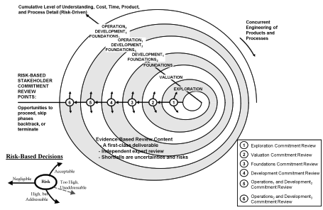
Each spiral will be concurrently, rather than sequentially, addressing requirements and solutions; products and processes; hardware, software and human factors aspects; and business case analysis of alternative product configurations or product line investments.
The stakeholders consider the risks and risk mitigation plans, and decide on a course of action. If the risks are acceptable and will be covered by risk mitigation plans, the project would proceed into the next spiral.
The development spirals after the first development commitment review follow the three-team incremental development approach for achieving both agility and assurance shown in Figure 2 and discussed in System Life Cycle Process Drivers and Choices.
Other Views of the Incremental Commitment Spiral Model (ICSM)
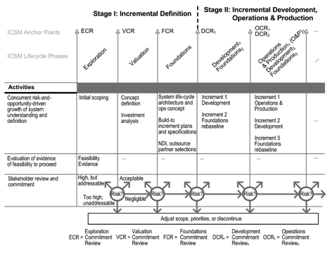
Figure 7 presents an updated view of the ICSM life cycle process recommended in the National Research Council “Human-System Integration in the System Development Process” study (Pew and Mavor 2007). It was called the Incremental Commitment Model (ICM) in the study.
The ICSM builds on the strengths of current process models, such as early verification and validation concepts in the V-model, concurrency concepts in the Concurrent Engineering model, lighter-weight concepts in the Agile and Lean models, risk-driven concepts in the spiral model, the phases and anchor points in the Rational Unified Process (RUP) (Kruchten 1999; Boehm 1996), and recent extensions of the spiral model to address SoS capability acquisition (Boehm and Lane 2007).
The top row of activities in Figure 7 indicates that a number of system aspects are being concurrently engineered at an increasing level of understanding, definition, and development. The most significant of these aspects are shown in Figure 8, an extension of a similar “hump diagram” view of concurrently engineered software activities developed as part of the RUP (Kruchten 1999).
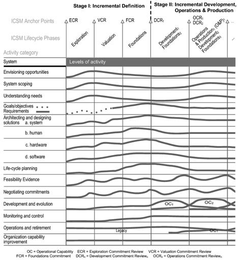
As with the RUP version, the magnitude and shape of the levels of effort will be risk-driven and likely to vary from project to project.
Figure 8 indicates that a great deal of concurrent activity occurs within and across the various ICSM phases, all of which needs to be synchronized and stabilized—a best-practice term taken from Microsoft Secrets (Cusumano and Selby 1996)—to keep the project under control.
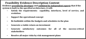
The review processes and use of independent experts are based on the highly successful AT&T Architecture Review Board procedures described in Maranzano et al. 2005. Figure 9 shows the content of the Feasibility Evidence Description. Showing feasibility of the concurrently-developed elements helps synchronize and stabilize the concurrent activities.
The Operations Commitment Review (OCR) is different in that it addresses the often much higher operational risks of fielding an inadequate system. In general, stakeholders will experience two to ten increase in commitment level while going through the sequence of ECR to DCR milestones, but the increase in going from DCR to OCR can be much higher. These commitment levels are based on typical cost profiles across the various stages of the acquisition life cycle.
Underlying ICSM Principles
ICSM has four underlying principles which must be used with the diagrams, as follows:
- Stakeholder value-based system definition and evolution
- Incremental commitment and accountability
- Concurrent system and software definition and development
- Evidence and risk-based decision making
Model Experience to Date
The National Research Council Human-Systems Integration study found that the ICSM processes and principles correspond well with best commercial practices (2008). Further examples are found in Pew and Mavor 2007, chap 5; Royce 1998, Appendix D; and the annual series of "Top Five Quality Software Projects" published in CrossTalk (2002-2005).
Primarily Interpersonal and Unconstrained Processes: Scrum and Agile
Figure 10 shows an example of Scrum as an agile process flow. As with most other agile methods, Scrum uses the Evolutionary Sequential process shown in Table 1 and described in Fixed-Requirements and Evolutionary Development Processes, in which systems capabilities are developed in short periods, usually around 30 days. The project then re-prioritizes its backlog of desired features and determines how many features the team (usually ten people or less) can develop in the next 30 days.
As shown in Figure 10, once the features to be developed for the current Scrum have been expanded (usually in the form of informal stories) and allocated to the team members, the team establishes a daily rhythm of starting with a short meeting at which each team member does about a one-minute summary of progress since the last Scrum meeting, potential obstacles, and plans for the upcoming day.

Architected Agile Methods
Over the last decade, several organizations have been able to scale up agile methods by using two layers of ten-person Scrum teams. This involves, among other things, having each Scrum team’s daily meeting followed up by a daily meeting of the Scrum team leaders discussing up-front investments in an evolving system architecture (Boehm et al. 2010). Figure 11 shows an example of the Architected Agile approach.

Agile Practices and Principles
Here are summaries of the general practices and principles shared by most agile methods. As seen with the Scrum and Architected Agile methods, generally-shared does not necessarily mean uniformly followed.
Iterative Development (any organization can improve its velocity to customer satisfaction):
- The project team understands, respects, works, and behaves within a defined SE process.
- The project is executed as fast as possible with minimum down time or staff diversion during the project; the critical path is managed.
- All key players are physically or electronically collocated; notebooks are team property and are available to all.
- Baseline management and change control are achieved by formal, oral agreements based on “make a promise, keep a promise” discipline — participants hold each other accountable.
- Opportunity exploration and risk reduction are accomplished by expert consultation and rapid model verification, coupled with close customer collaboration; software development is done in a rapid development. environment, while hardware is developed in a multi-disciplined model shop.
- A culture of constructive confrontation pervades the project organization; the team takes ownership for success; it is never “someone else’s responsibility."
Agile Development principles (adapted for SE) are as follows (Principles behind the Agile Manifesto 2009):
- First, satisfy the customer through early and continuous delivery of valuable software (and other system elements).
- Welcome changing requirements, even late in development; agile processes harness change for the customer’s competitive advantage.
- Deliver working software (and other system elements) frequently, from a couple of weeks to a couple of months, with a preference to the shorter timescale.
- Business people and developers must work together daily throughout the project.
- Build projects around motivated individuals, give them the environment, support their needs, and trust them to get the job done.
- The most efficient and effective method of conveying information is face-to-face conversation.
- Working software (and other system elements) is the primary measure of progress.
- Agile processes promote sustainable development; the sponsors, developers, and users should be able to maintain a constant pace indefinitely.
- Continuous attention to technical excellence and good design enhances agility.
- Simplicity—the art of maximizing the amount of work not done—is essential.
- The best architectures, requirements, and designs emerge from self-organizing teams.
At regular intervals, the team reflects on how to become more effective, then tunes and adjusts its behavior accordingly.
Concluding Remarks
While there are a number of different models describing the project environment, the Spiral model and the Vee model have become the dominant approaches to visualizing the development process. Both the Vee and the Spiral are useful models that emphasize different aspects of the process.
The majority of projects will use IID. Evolutionary development is particularly appropriate to use on new products coming from research whether in the commercial or government environment.
References
Citations
Boehm, B. 1996. "Anchoring the Software Process." IEEE Software 13(4): 73-82.
Boehm, B. and J. Lane. 2007. “Using the Incremental Commitment Model to Integrate System Acquisition, Systems Engineering, and Software Engineering.” CrossTalk 20(10) (October 2007), p.4-9.
Boehm, B. and R. Turner. 2004. Balancing Agility and Discipline. New York, NY, USA: Addison-Wesley.
Castellano, D.R. 2004. “Top Five Quality Software Projects.” CrossTalk 17(7) (July 2004): 4-19. Available at: http://www.crosstalkonline.org/storage/issue-archives/2004/200407/200407-0-Issue.pdf
Dingsoyr, T., T. Dyba., and N. Moe (eds.). 2010. "Agile Software Development: Current Research and Future Directions." Chapter in B. Boehm, J. Lane, S. Koolmanjwong, and R. Turner. Architected Agile Solutions for Software-Reliant Systems. New York, NY, USA: Springer.
Fairley, R. 2009. Managing and Leading Software Projects. New York, NY, USA: John Wiley & Sons.
Forsberg, K. 1995. “'If I Could Do That, Then I Could…’ System Engineering in a Research and Development Environment,” Proceedings of the Fifth International Council on Systems Engineering (INCOSE) International Symposium. 22-26 July 1995. St Louis, MO, USA.
Forsberg, K., H. Mooz, and H. Cotterman. 2005. Visualizing Project Management. 3rd ed. New York, NY, USA: John Wiley & Sons.
Jarzombek, J. 2003. “Top Five Quality Software Projects.” CrossTalk 16(7) (July 2003): 4-19. Available at: http://www.crosstalkonline.org/storage/issue-archives/2003/200307/200307-0-Issue.pdf.
Kruchten, P., 1999. The Rational Unified Process. New York, NY, USA: Addison Wesley.
Maranzano, J., et al. 2005. “Architecture Reviews: Practice and Experience.” IEEE Software 22(2): 34-43.
Pew, R. and A. Mavor (eds.). 2007. Human-System Integration in The System Development Process: A New Look. Washington, DC, USA: The National Academies Press.
Spruill, N. 2002. “Top Five Quality Software Projects.” CrossTalk 15(1) (January 2002): 4-19. Available at: http://www.crosstalkonline.org/storage/issue-archives/2002/200201/200201-0-Issue.pdf.
Stauder, T. (pub.). “Top Five Department of Defense Program Awards.” CrossTalk 18(9) (September 2005): 4-13. Available at http://www.crosstalkonline.org/storage/issue-archives/2005/200509/200509-0-Issue.pdf.
Primary References
Beedle, M., et al. 2009. "The Agile Manifesto: Principles behind the Agile Manifesto". in The Agile Manifesto [database online]. Accessed 2010. Available at: www.agilemanifesto.org/principles.html
Boehm, B. and R. Turner. 2004. Balancing Agility and Discipline. New York, NY, USA: Addison-Wesley.
Fairley, R. 2009. Managing and Leading Software Projects. New York, NY, USA: J. Wiley & Sons.
Forsberg, K., H. Mooz, and H. Cotterman. 2005. Visualizing Project Management. 3rd ed. New York, NY, USA: J. Wiley & Sons.
INCOSE. 2011. Systems Engineering Handbook: A Guide for System Life Cycle Processes and Activities. Version 3.2.1. San Diego, CA, USA: International Council on Systems Engineering (INCOSE), INCOSE-TP-2003-002-03.2.1.
Lawson, H. 2010. A Journey Through the Systems Landscape. Kings College, UK: College Publications.
Pew, R., and A. Mavor (eds.) 2007. Human-System Integration in the System Development Process: A New Look. Washington, DC, USA: The National Academies Press.
Royce, W. E. 1998. Software Project Management. New York, NY, USA: Addison Wesley.
Additional References
Anderson, D. 2010. Kanban. Sequim, WA, USA: Blue Hole Press.
Baldwin, C. and K. Clark. 2000. Design Rules: The Power of Modularity. Cambridge, MA, USA: MIT Press.
Beck, K. 1999. Extreme Programming Explained. New York, NY, USA: Addison Wesley.
Beedle, M., et al. 2009. "The Agile Manifesto: Principles behind the Agile Manifesto" in The Agile Manifesto [database online]. Accessed 2010. Available at: www.agilemanifesto.org/principles.html
Biffl, S., A. Aurum, B. Boehm, H. Erdogmus, and P. Gruenbacher (eds.). 2005. Value-Based Software Engineering. New York, NY, USA: Springer.
Boehm, B. 1988. “A Spiral Model of Software Development.” IEEE Computer 21(5): 61-72.
Boehm, B. 2006. “Some Future Trends and Implications for Systems and Software Engineering Processes.” Systems Engineering 9(1): 1-19.
Boehm, B., A. Egyed, J. Kwan, D. Port, A. Shah, and R. Madachy. 1998. “Using the WinWin Spiral Model: A Case Study.” IEEE Computer 31(7): 33-44.
Boehm, B., J. Lane, S. Koolmanojwong, and R. Turner. 2011 (in press). Embracing the Spiral Model: Creating Successful Systems with the Incremental Commitment Spiral Model. New York, NY, USA: Addison Wesley.
Checkland, P. 1981. Systems Thinking, Systems Practice. New York, NY, USA: Wiley.
Stauder, T. 2005. “Top Five Department of Defense Program Awards.” CrossTalk 18(9) (September 2005): 4-13. Available at http://www.crosstalkonline.org/storage/issue-archives/2005/200509/200509-0-Issue.pdf.
Castellano, D.R. 2004. “Top Five Quality Software Projects.” CrossTalk 17(7) (July 2004): 4-19. Available at: http://www.crosstalkonline.org/storage/issue-archives/2004/200407/200407-0-Issue.pdf
Jarzombek, J. 2003. “Top Five Quality Software Projects.” CrossTalk 16(7) (July 2003): 4-19. Available at: http://www.crosstalkonline.org/storage/issue-archives/2003/200307/200307-0-Issue.pdf.
Spruill, N. 2002. “Top Five Quality Software Projects.” CrossTalk 15(1) (January 2002): 4-19. Available at: http://www.crosstalkonline.org/storage/issue-archives/2002/200201/200201-0-Issue.pdf.
Crosson, S. and B. Boehm. 2009. “Adjusting Software Life Cycle Anchorpoints: Lessons Learned in a System of Systems Context.” Proceedings of the Systems and Software Technology Conference, 20-23 April 2009, Salt Lake City, UT, USA.
Dingsoyr, T., T. Dyba. and N. Moe (eds.). 2010. "Agile Software Development: Current Research and Future Directions.” Chapter in B. Boehm, J. Lane, S. Koolmanjwong, and R. Turner, Architected Agile Solutions for Software-Reliant Systems. New York, NY, USA: Springer.
Dorner, D. 1996. The Logic of Failure. New York, NY, USA: Basic Books.
Faisandier, A. 2011 (unpublished). Engineering and Architecting Multidisciplinary Systems.
Forsberg, K. 1995. "'If I Could Do That, Then I Could…' System Engineering in a Research and Development Environment.” Proceedings of the Fifth Annual International Council on Systems Engineering (INCOSE) International Symposium. 22-26 July 1995. St. Louis, MO, USA.
Forsberg, K. 2010. “Projects Don’t Begin With Requirements.” Proceedings of the IEEE Systems Conference. 5-8 April 2010. San Diego, CA, USA.
Gilb, T. 2005. Competitive Engineering. Maryland Heights, MO, USA: Elsevier Butterworth Heinemann.
Goldratt, E. 1984. The Goal. Great Barrington, MA, USA: North River Press.
Hitchins, D. 2007. Systems Engineering: A 21st Century Systems Methodology. New York, NY, USA: Wiley.
Holland, J. 1998. Emergence. New York, NY, USA: Perseus Books.
ISO/IEC. 2010. Systems and Software Engineering, Part 1: Guide for Life Cycle Management. Geneva, Switzerland: International Organization for Standardization (ISO)/International Electronical Commission (IEC), ISO/IEC 24748-1:2010.
ISO/IEC 2008. Systems and Software Engineering -- System Life Cycle Processes. Geneva, Switzerland: International Organisation for Standardisation / International Electrotechnical Commissions. ISO/IEC/IEEE 15288:2008.
ISO/IEC. 2003. Systems Engineering — A Guide for The Application of ISO/IEC 15288 System Life Cycle Processes. Geneva, Switzerland: International Organization for Standardization (ISO)/International Electronical Commission (IEC), ISO/IEC 19760:2003 (E).
Kruchten, P. 1999. The Rational Unified Process. New York, NY, USA: Addison Wesley.
Landis, T. R. 2010. Lockheed Blackbird Family (A-12, YF-12, D-21/M-21 & SR-71). North Branch, MN, USA: Specialty Press.
Madachy, R. 2008. Software Process Dynamics. New York, NY, USA: Wiley.
Maranzano, J., et al. 2005. “Architecture Reviews: Practice and Experience.” IEEE Software 22(2): 34-43.
National Research Council of the National Academies (USA). 2008. Pre-Milestone A and Early-Phase Systems Engineering. Washington, DC, USA: The National Academies Press.
Osterweil, L. 1987. “Software Processes are Software Too.” Proceedings of the SEFM 2011: 9th International Conference on Software Engineering. Monterey, CA, USA.
Poppendeick, M. and T. Poppendeick. 2003. Lean Software Development: an Agile Toolkit. New York, NY, USA: Addison Wesley.
Rechtin, E. 1991. System Architecting: Creating and Building Complex Systems. Upper Saddle River, NY, USA: Prentice-Hall.
Rechtin, E., and M. Maier. 1997. The Art of System Architecting. Boca Raton, FL, USA: CRC Press.
Schwaber, K. and M. Beedle. 2002. Agile Software Development with Scrum. Upper Saddle River, NY, USA: Prentice Hall.
Warfield, J. 1976. Societal Systems: Planning, Policy, and Complexity. New York, NY, USA: Wiley.
Womack, J. and D. Jones. 1996. Lean Thinking. New York, NY, USA: Simon and Schuster.
