Difference between revisions of "Logical Architecture"
(No difference)
|
Revision as of 20:56, 9 August 2011
Introduction, Definition and Purpose of Architectural Design
Introduction - Architectural design explores, defines, and formalizes the solutions that meet the System Requirements and selects the optimal solution, taking those requirements into account. Design is in fact the core of Systems Engineering.
Definition and Purpose - The design of a system is the creation of a global solution based on principles and concepts logically related and consistent to each others. The solution owns properties and characteristics satisfying as much as possible the problem expressed by a set of System Requirements. It is implementable through technologies.
The properties and characteristics of a complex system that encompasses several disciplines are numerous. They can be classified and modeled during the design activities in sectors or views such as, but not limited to, functional, temporal, behavioral, performance, operational, environmental, and structural - see Fundamentals of System Definition topic, System Architecture and System Design sections.
The designer or architect is helped a lot when system requirements are classified with a design properties oriented classification as suggested in System Requirements Definition topic, section "Classification of System Requirements".
Some essential issues to be approached during the design of systems are related to the properties, characteristics and goals listed below:
- Functional, behavioral, temporal views - The functional modeling of the solution, as independent as possible from the implementation technologies, is an essential step toward working out an optimal physical solution. This functional model is established according to various aspects of transformations (functions and input-output flows ) and considers the behavior of the system (operational modes , transitions of modes , and trigger events), otherwise known as the scenarios of the system operation (use cases). A temporal and decision monitoring model supplements well the functional and behavioral models to organize the in service management of the system in order to achieve permanently its mission and purpose .
- Performance, operational, environmental, structural views - The projection or allocation of functional, behavioral, temporal models onto a physical architecture , dependent of the implementation technologies, includes the definition of systems and system elements and physical connections (physical interfaces ) that owns together design properties such as:
- structural properties (simplicity, modularity, adaptability, scalability, reusability, portability, commonality, expandability, etc.),
- effectiveness/performance levels, accuracy, etc.,
- operational characteristics (usability, availability, maintainability, reliability, testability, robustness, interoperability, integrity, generality, trainingetc.),
- environmental characteristics (heatproof, shockproof, electrical resistance, radiation resistance, etc.).
- Confidence in the solution - The confidence having correctly designed the architecture and found the optimal option, given the complete set of System Requirements. This essential aspect is related to the assessment of the properties and characteristics of the system that are performed during design; refer to System Analysis topic.
The Physical Architectural models should cover properties such as listed above. But it is impossible that a single model represent all properties. A today issue is the consistency of all models that represent the global solution.
Principles about Architectural Design
This section provides a short explanation of the general mechanism of intellectual creation and then focus on known concepts and/or patterns by system designers or architects such as interface, function, input-output-control flow, dynamics, temporal and decision hierarchy, allocation and partitioning, emerging properties, etc.
Intellectual creation principles and patterns
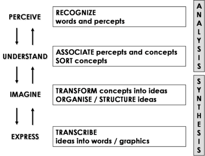
The intellectual creation works with more or less short "analysis – synthesis" cycles. We analyze objects, ideas, their relationships, and then we try to express or represent synthesis more or less successfully. Figure 1 summarizes this mechanism:
- Analysis includes two major tasks: perception and understanding.
- Perception consists to identify words, figures, drawings, ideas, etc.
- Understanding consists to associate what is perceived to existing concepts recorded in our memory, sorting the concepts to use them or not.
- Synthesis includes also two major tasks: imagination and expression.
- Imagination consists to transform concepts into images, ideas, then organizing, structuring, globalize, clarify and precise them. If the concept has not been recognized during the analysis, it does not exist in our mind, but it can be created by associations of existing concepts by similarity or aggregation, modifications, etc.
- Expression consists to transcribe ideas and images in words, drawings, symbols, sounds using standards known by a concerned community.
Figure 1. Intellectual creation principles and mechanism (Faisandier, 2011)
This mechanism is used at anytime in engineering activities and in particular when designing architectural views. To design a functional architecture , the designer analyses System Requirements, recognizes concepts of Functions, Input-Output Flows, and then imagines how to organize them and represent Scenarios as functional flow diagrams using standard representations. If the sequence of functions does not exist, the designer is able to use existing "patterns" and/or create new ones by similarity, aggregation, modification, etc. The same mechanism applies to a Physical Architecture understanding Functions and imagining or recognizing System Elements supporting the functions taking into account properties and characteristics, and then express with textual or graphical models for representation, etc.
Note: The term "pattern" originates as an architectural concept by Christopher Alexander – refer to (Alexander, Christopher; Sara Ishikawa, Murray Silverstein, Max Jacobson, Ingrid Fiksdahl-King, Shlomo Angel. 1977). In software engineering, a design pattern is a general reusable solution to a commonly occurring problem in software design. A design pattern is not a finished design that can be transformed directly into code. It is a description or template for how to solve a problem that can be used in many different situations – refer to (Gamma, Erich; Richard Helm, Ralph Johnson, and John Vlissides. 1995). As software engineering, several domains adopted the notion of pattern and defined their basic ones. Systems Engineering would have to do the same for every topic or view.
Concept of Interface
The concept of interface is probably one of the most important to take into account when designing the architecture of the system of interest (soi) . From an etymology point of view, the term “interface” comes from the Latin words "inter" and "face" and means “to do something between things”. Therefore, the fundamental aspect of an interface is functional and is defined as inputs and outputs of functions. As the Functions are performed by physical elements (systems or System Elements), the Inputs/Outputs Flows of the functions are also carried by physical elements, called Physical Interfaces. Consequentially, the engineer must consider both the functional and physical aspects in the complete notion of interface. A detailed analysis of a complete interface shows that one needs to consider also the Function “send,” located in one of the System Element, the Function “receive,” located in the other one, and the Function “carry,” performed by the Physical Interface which supports the Input/Input Flow – see Figure 2.
Figure 2. Complete Interface Representation (Faisandier, 2011)
In the context of complex exchanges between some System Elements, a protocol is seen as a Physical Interface which carries or supports the exchanges of data (functional interface).
Functional / Logical Architecture
Concept of Function
A Function is an action that transforms inputs and generates outputs such as materials, energies, or information (or a combination of them). These inputs and outputs are the flow items exchanged between the functions. The general mathematic notation of a function is y = ƒ(x,t) and can be represented graphically – refer to section Methods and Modeling Techniques.
The design activities shall proceed from a functional framework, specifically in the case of the processes dealing with control-command, data processing, or services. In order to define the complete set of functions of the system, one must identify all the functions necessitated by the system and derived requirements as well as the corresponding inputs and outputs exchange driven by those functions. These two kinds of functions are:
- The functions directly deduced from the functional requirements and from the interface requirements. They express the expected services of a system to meet the System Requirements.
- The derived functions issued from the alternative solutions of Physical Architecture as the result of the design. They depend on technology choice to implement the Functional Architecture.
Functions hierarchy – Decomposition of Functions
At the highest level of a hierarchy, it is possible to represent a system as a unique main function (defined as the system's mission) just like a "black box." In order to understand in detail what the system does, this "head-of-hierarchy" is broken down into sub-functions grouped to form a sub-level of the hierarchy, and so on. The functions of the last level of a functional hierarchy can be called leaf-functions. Hierarchies (or breakdowns) decompose a complex or global function into a set of functions for which the physical solutions are known or possible to imagine.
Input/Output and Control Flows – Interfaces between Functions
The decomposition into functional hierarchy is an interesting way of understanding the system, but it represents an incomplete part of the Functional Architecture because it does not represent the exchanged flows of inputs and outputs. To get a more complete view, representations of the Functional Architecture should be able to model the various transformations operated by the system, using diagrams such as Functional Flow Block diagrams (FFBD)(Oliver, Kelliher, and Keegan. 1997), or Activity Diagram of SysML (OMG. 2010).
In SE three types of Input/Output Flows exchanged are considered: material, energy, and information.
Control Flow (Trigger)
The control flow is an element that activates a function as a condition of its execution. The state of this element (or the condition it represents) activates or deactivates the function (or elements thereof). A control flow can be a signal, an event such as position "on", an alarm or a trigger, a temperature variation, the push of a key on a keyboard, etc.
Note: in SysML (OMG. 2010) all interactions are initiated by signals; there five kinds of signals: creation event, destruction event, asynchronous message, synchronous message, duration constraints.
Concept of Dynamics
The preponderance of mathematics consists of continuous functions that are generally solved though differential equations. In SE, one considers also the set of functions that interact between themselves and with functions outside of the system. Since functions start and stop their execution depending on events, triggers, or durations, the discontinuous aspect of functions is a major consideration when designing the Functional Architecture.
Modeling using only functional hierarchy decomposition is insufficient to give a complete idea of what the system will do. A Function is action, transformation, and dynamics, so it is necessary to consider the exchanges between the functions, as well as the reactions of the system in its context and operational environment, through control flows, Scenarios, and behaviors of functions, states, or Operational Modes.
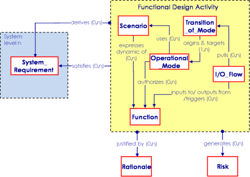
Scenario of Functions - A Scenario is a chain of Functions performed as a sequence that synchronizes the functions between them, using their control flows to achieve a global transformation of inputs into outputs. A Scenario of Functions expresses the dynamic of an upper level Function; inversely, a Function can be expressed dynamically by a Scenario of (sub) Functions. The Functional Architecture is worked out with Scenarios for each level of the functional hierarchy and for each level of the system hierarchy. The coherent combination of the Scenarios can be considered as the global Functional Architecture of the system.
Operational State/Operational Mode – A Scenario of Functions can be viewed by abstracting the transformation of inputs into outputs of each function and focusing on the active or non-active state of the function and on its controls. Now, in a discussion of Operational Mode, the focus is on a scenario of modes. A scenario of modes is a chain of modes performed as a sequence of transitions between the various modes of the system. The transition from one mode to another one is triggered by the arrival of a control flow (event, trigger). An action (function) can be generated within a transition between two modes, following the arrival of an event or a trigger.
Functional Design Patterns
When designing Scenarios or Functional Architectures, the designer has to recognize and to use known models to perform the expected transformations. Patterns are generic basic models, more or less sophisticated depending of the complexity of the treatment. A pattern can be represented with different notations. Functional design patterns could be classified into several categories, such as examples:
- Basic patterns linking functions: sequence, iteration, selection, concurrence, multiple exits, loop with exit, replication without monitoring, replication with monitoring, etc.
- Complex patterns: monitor a treatment, exchange a message, Man Machine Interface, mutual exchanges, states-transition monitoring, real-time monitoring of processes, queue management, continuous monitoring with supervision, etc.
- Failure detection, identification, recovery (FDIR) patterns: general FDIR pattern, passive redundancies, active redundancies, semi-active redundancies, continuation of treatment in degraded performance, etc.
- Etc.
Temporal and Decision Hierarchy Concept
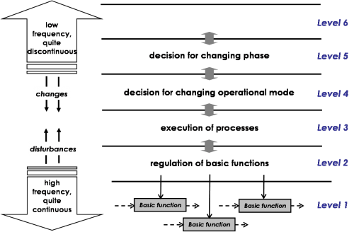
Not every Function of a system is performed at the same frequency. It changes depending on the time and the ways functions are started and executed. One must therefore consider several classes of performance.
There are synchronous functions, that are executed cyclically, and asynchronous functions, that are executed when an event or trigger happens. The decision monitoring inside a system follows the same temporal classification because decisions are related to functions.
"Real-time" systems and command/control systems combine the cyclic operations (synchronous) and the factual aspects (asynchronous). The cyclic operations consist of sharing out the execution of the functions according to frequencies, which depend on the constraints of capture, or dispatching the input/output and control flows. Two types of asynchronous events can be distinguished:
- The disturbances on the high frequencies (bottom of Figure 3) - the decisions are made at the level they occur or at the immediate upper level. The goal is to ensure the disturbances do not go up in the low frequencies so that the system continues to achieve its mission objectives. This is the way to introduce exception operations. The typical example related to the operations concerns breakdowns or failures.
- The changes happening on the low frequencies (top of Figure 3) - the decisions of change are made at the upper levels. The goal is to transmit them towards the bottom levels to implement the modifications. A typical example relates to operator actions, maintenance operations, etc.
Figure 3. Temporal and Decision Hierarchy Levels (Faisandier, 2011)
Physical Architecture
Allocation of Functional Elements to Physical Elements and Partitioning
A complex system composed of thousands of physical and intangible parts is structured in layers of systems and System Elements. To be mastered easily the number of elements in decomposition is limited to a few ones – see Figure - Hierarchical decomposition of a system-of-interest (ISO-IEC 15288) in the Introductory Paragraphs of System Definition KA.
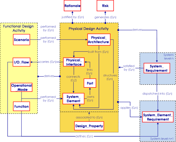
A system Physical Architecture is a structure of the System of Interest that identifies the System Elements with their Physical Interfaces. Physical Architecture and its elements exist in any kind of system, even in systems of services (human roles, infrastructures, procedures, protocols, etc.), organizations or enterprises (departments, sections, divisions, projects, procedures, protocols, etc.), or systems-intensive software (pieces of code, objects, databases, application protocols interface, etc.).
The System Elements of the system perform the Functions, and the Physical Interfaces between system elements carry the Input/Output Flows and control flows. Partitioning and allocation are activities to decompose, gather, or separate Functions in order to be able to identify feasible System Elements that could perform the Functions of the system.
Criteria to Partition and Allocate Functions onto System Elements
Partitioning and allocation use criteria to find potential affinities between the functions. There are several criteria provided by the list of System Requirements. Some of the criteria include the periodicity of function, whether functions are subjected to similar effectiveness measures, whether they have commonalities in input, output, or control flows, whether similar transformations occur, whether functions occur in similar environments, the level of reuse of system elements, and/or project or enterprise constraints.
The partitioning of functions stops when the designer is able to identify one or several system elements that could perform the function or a set of functions. Either the system element exists, is re-usable, or can be developed and technically implemented.
Designing Physical Candidate Architectures
The existence of several candidate arrangements of system elements that might potentially implement a Function feed the list of candidate Physical Architectures that might be selected for the preferred Physical Architecture. All viable Physical Architectures should completely implement all required system Functions. The preferred Physical Architecture represents the optimum design.
For a specific system level, the number of levels of decomposition of the functions might not exceed three or four because the sub-functions reside in the lower system levels. Even if the designer identifies more than ten leaf system elements to constitute the architecture of the current system level, he or she must synthesize the set into a single level of 7 + or – 2 higher level of systems and/or system elements. Because design of systems is achieved by designers, these recommended limitations come from the short term memory of a median human being. They allow to master the handled elements, their interfaces, their interrelationships and to navigate in the architecture for impact analysis, flow analysis as examples.
Synthesis is done by grouping the leaf system elements to constitute a set of (sub)systems. It must be done according to design criteria or principles such as reduction of the number of physical interfaces, modularity, testability of system elements, maintainability, compatibility of technologies, usability, consumption of means or resources, emerging properties control (see section further), etc.
Evaluating and Selecting the Preferred Alternative
The goal of physical design activities is to achieve and provide the best possible set of system elements and the “best” architecture. The “best” means to define the solution that answers, at best, all the requirements, depending on the agreed limits or margins of each requirement. To do so, there is no other way than to produce several architectures, compare them, and select the most suitable one. Depending on the kind of system, certain analyses (efficiency, dependability, cost, risks, etc.) are required to get sufficient data that characterize the global or detailed behavior of the candidate architectures of the system, regarding the System Requirements. Those analyses are gathered behind the terms System Analysis.
Design activity includes optimization to obtain a balance among Design Properties, cost, risks, etc. The architectural structure of a system is determined more strongly by non-functional requirements (performance, safety, security, environmental conditions, constraints, etc.) than by functions. There may be many ways to achieve functions but fewer ways to satisfying non-functional requirements.
Emerging Properties
The notion of emerging property (see emergence ) is used during the design of the system to highlight the necessary derived functions and internal physical or environmental constraints of the system. The corresponding “derived requirements” result in particular from the studies of these emerging properties. They should be added to the System Requirements baseline when they impact the System of Interest (SOI).
The System Elements that compose the System of Interest interact between themselves and can create desirable or undesirable phenomena called "emerging properties," such as interference or resonance. The definition of the system includes an analysis of the interactions between the System Elements in order to prevent the undesirable properties (negative behaviors) and reinforce the desirable ones (positive behaviors).
A property which emerges from a system can have various origins: from a single System Element, from several System Elements, or from the interaction between several System Elements.
The emerging properties of a system can be classified as in (Thome, B. 1993) - see Table 1.
Table 1 - Classification of emerging properties NEW TABLE
Systems of Systems Architecting
Considering a set of existing Systems of Interest that have their own existence in their own context of use, the issue is to know if it is possible to constitute a System of Interest that includes those as System Elements. The higher level system has a Mission, a Purpose, a context of use, objectives and architectural elements. The engineering of such systems is a little bit particular and includes generally reverse engineering and top down approach. It is the case when upgrading facilities in the frame of a company using information technology keeping legacy systems. The architecture activity combines a top-down approach (as for a standard system), but also a bottom-up approach which is induced by the necessity to integrate existing or legacy systems on which no or very few modifications can be applied. So, additional tasks consist to identify these existing or legacy systems, to determine their capabilities and interfaces. The architecture activity has to answer two questions:
- how to fulfill requirements of the new System of Interest?
- how to manage with legacy systems?
The characteristics of a system of systems (sos) are provided in the Systems of Systems (SoS) KA, and are considered as requirements or constraints when designing their architecture.
Process Approach – Architectural Design
Purpose and Principle of the approach
The purpose of the Architectural Design Process is to synthesize a solution that satisfies the System Requirements (ISO/IEC. 2008).
The architectural solution consists of both a Functional / logical Architecture (expressed as a set of Functions, Scenarios, and/or Operational Modes) and a Physical Architecture (expressed as a set of systems and System Elements physically connected between them) associated to a set of Design Properties.
Transition from System Requirements to Physical Architecture
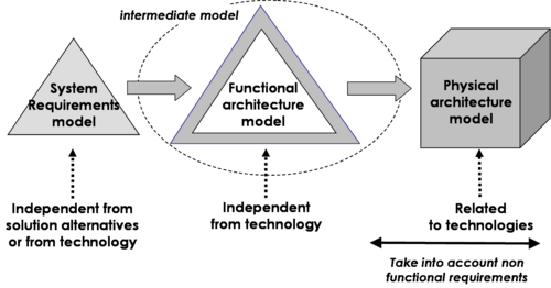
The aim of the approach is to progress from the System Requirements baseline – representing the problem from a supplier/designer point of view, and as much as possible independent of technology - to an intermediate model of Functional Architecture - dependent on design decisions - then to allocate the elements of the Functional Architecture to the elements of potential Physical Architectures. The design decisions and the technological solutions are selected according to performance criteria and non-functional requirements such as the operational conditions and life cycle constraints (for example: environmental conditions or maintenance constraints) – see Figure 4.
Figure 4. Progressive Approach for Designing (Faisandier, 2011)
Iterations between Functional and Physical Architectures Design
The design activities require spending several iterations from the functional design to the physical design and vice versa until both functional and physical architectures are exhaustive and consistent.
The first design activity is always the creation of a functional design that is based on the nominal Scenarios. The goal is to get a first model that could achieve the mission of the system. The physical design then enables the engineer to determine the main system elements that will perform these Functions and to organize them into a Physical Architecture.
A second functional design loop allows taking into account the allocations of the Functions onto System Elements and the derived functions coming from the physical solution choices, as well as supplementing the initial functional model by introducing other and/or altered modes, failure analyses, and every operational requirement not taken into account in the first loop. The derived Functions must, in their turn, be allocated to System Elements, and this, in turn, affects the physical design.
Obviously, other design loops must be considered to produce an exhaustive and consistent functional and physical solution. During design, technological choices conduct potentially to new Functions, new Input/Output and control Flows, and new Physical Interfaces. These new elements can conduct to the creation of new System Requirements, called “derived requirements”, which become part of the requirements baseline.
Generic inputs and outputs of the design process
Because of the necessary iterative execution of the design, the inputs and outputs of the process evolve incrementally. The generic inputs include of course the System Requirements, but also the generic design patterns that the designer identifies and uses to answer the requirements, the outcomes from the System Analysis, and the feedback from the System Verification and Validation.
The generic outputs are the selected Functional and Physical Architectures of the System of Interest (SOI), the (stakeholder) requirements of every System Element that comprises the Physical Architecture of the System of Interest, the Interface Requirements between the System Elements, and the rejected solutions elements.
ADD eventually ACTION RELATED TO COMMENTs 2228, 2229
Activities of the Process
ADD ACTION RELATED TO COMMENT 2491
Major activities and tasks performed during this process include:
- Define the functional architecture of the system:
- Identify Functions, Input/Output Flows, Operational Modes, Transition of Modes, and operational Scenarios from the System Requirements by analyzing the functional, interface, and operational requirements.
- Define the necessary inputs and controls (energy, material, and data flows) to each Function and the outputs generated thereby; deduce the necessary Functions which use, transform, move, and generate the Input/Output Flows.
- Allocate performance, effectiveness, and constraints requirements to Functions and to Input, Output, and control Flows.
- Design candidate Functional Architectures using the previous defined elements to model Scenarios of functions and/or model sequences of Operational Modes and Transition of Modes. Integrate the Scenarios of functions in order to get a complete picture of the dynamic behavior of the system and allocate the temporal constraints. Decompose the functional elements as necessary to look towards implementation. Perform functional failure modes and effects analysis and update the Functional Architecture as necessary.
- Select the Functional Architecture by assessing the candidate Functional Architectures against assessment criteria (related to requirements) and comparing them. Use System Analysis Process to perform the assessments – see System Analysis topic.
- Synthesize the selected Functional Architecture, verifying its dynamic behavior. Identify the derived functional elements created for the necessity of design.
- Establish traceability between System Requirements and Functional Architecture elements.
- Define the Physical Architecture of the system. That is:
- Search for System Elements able to perform the Functions as well as Physical interfaces to carry the Input, Output, and control Flows; ensure the System Elements exist or must be engineered. Use partitioning method to perform this allocation (when it is impossible to identify a System Element that performs a Function, decompose the function till it is possible to identify implementable System Elements).
- Design candidate Physical Architectures using the previously-defined elements to model networks of System Elements and Physical Interfaces. For each candidate, this requires the working out of a low-level Physical Architecture with the elementary System Elements. Because these are generally too numerous (ten or more) they have to be grouped into higher-level System Elements, also called systems. It is then possible to work out a high-level Physical Architecture with these systems and System Elements.
- Select the most suitable Physical Architecture by assessing the candidate Physical Architectures against Assessment Criteria (related to non functional requirements) and comparing them. Use the System Analysis Process to perform the assessments – see System Analysis topic.
- Synthesize the selected Physical Architecture, verifying that it satisfies the System Requirements and is realistic. Identify the derived physical elements and functional elements created for the necessity of design. Establish traceability between System Requirements and physical architecture elements and allocation matrices between functional and physical elements.
- Feedback the architectural design and the system requirements. That is:
- Model the “allocated functional architecture” onto systems and system elements if such a representation is possible.
- Define derived functional and physical elements induced by the selected functional and physical architectures. Define the corresponding derived requirements and allocate them on appropriate functional and physical architectures elements. Incorporate these derived requirements in the requirements baselines of the systems impacted.
- Prepare the technical elements for the acquisition of each system or system element:
- Define the mission and objectives of the system or System Element from the Functions allocated to the system or System Element and the allocation of performance and effectiveness to the system or System Element, respectively.
- Define the Stakeholder Requirements for this system or System Element (the concerned stakeholder being the System of Interest). Additional discussion on the development of the stakeholder requirements can be found in Mission Analysis and Stakeholders Requirements topic.
- Establish traceability between the Stakeholder Requirements of the system or System Element and the design elements of the System of Interest. This allows the traceability of requirements between two layers of systems.
Artifacts and Ontology Elements
This process may create several artifacts such as:
- System Design Document (describes the selected functional and physical architectures)
- System Design Justification Document (traceability matrices and design choices)
- System Element Stakeholder Requirements Document (one for each system or system element of the SOI)
- System Elements Interface Requirements Document (interfaces between the system elements of the SOI)
Note: The interfaces between the System Elements of the System of Interest are normally described in the System Design Document and then can be grouped in the System Elements Interface Requirements Documents for interfaces management purpose.
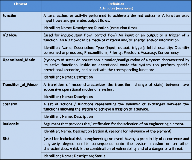
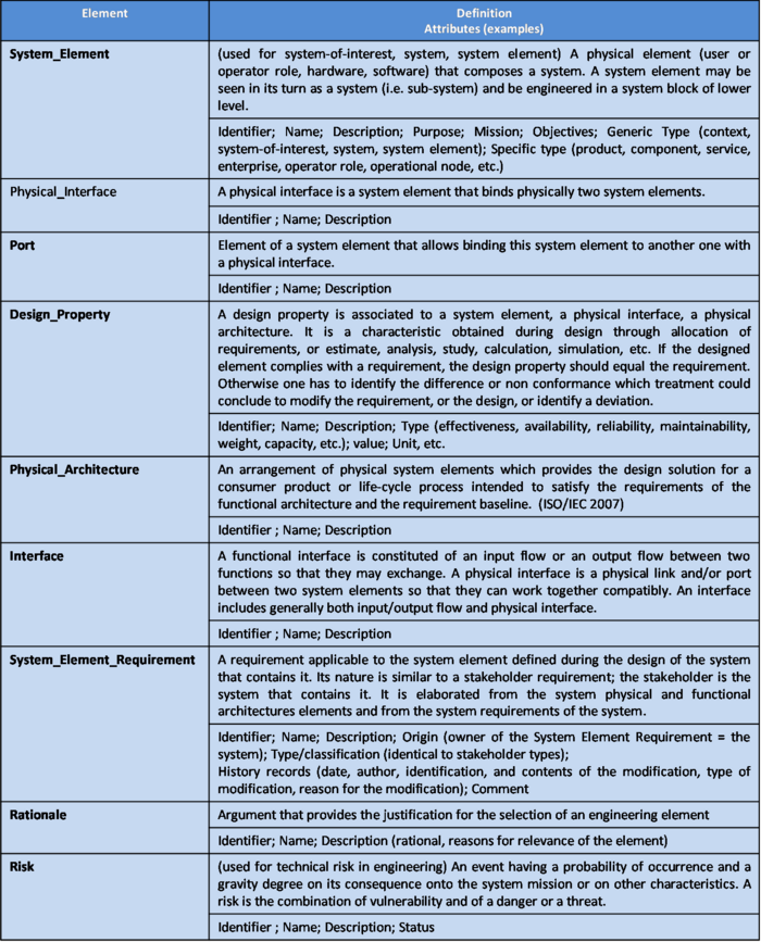
This process handles the ontology elements of Table 2 for System Functional Design and of Table 3 for System Physical Design.
Table 2. Main ontology elements as handled within System Functional Design
Note: The element Scenario is used for Functional Architecture, because as defined a Scenario includes a large set of functional and behavioral elements: flows of functions, flows of inputs-outputs, and flows of controls (triggers) arranged to model the transformations performed by the system and its behavior. Sequences of Operational Modes and Transition of Modes can be used alternatively depending of the used modeling techniques.
The main relationships between ontology elements of Functional Design are presented in Figure 5.
Figure 5. Functional Design elements relationships with other engineering elements (Faisandier, 2011)
Table 3. Main ontology elements as handled within System Physical Design
Note: The element "interface" may include both functional aspects (I/O Flow) and physical aspects (Physical Interface). It can be used for technical management purpose, for example to generate Interface Description Documents. It is not represented on the figures.
Note: The System Element Requirements become one part of the Stakeholder Requirements applicable to the System Element of the lower layer of decomposition.
The main relationships between ontology elements of Physical Design are presented in the Figure 6.
Figure 6. Physical Design elements relationships with other engineering elements (Faisandier, 2011)
Checking and Correctness of Architectural Design
The main items to be checked during design concern functional and physical architectures.
Concerning functional design, check that:
- Every functional and interface requirement corresponds to one or several functions.
- The outputs of functions correspond to submitted inputs.
- Every function produces at least one output.
- Functions are triggered by control flows as needed.
- Functions are sequenced in the right order and synchronized.
- The execution duration of the functions is in the range of the effectiveness or performance requirements.
- All requested operational scenarios are taken into account.
- The simulation of the functional architecture is complete in every possible case and shows that the consummation of input flows and the production of output flows are correctly sized (when simulation of models is possible).
Concerning physical design, check that:
- Every system element performs one or several functions of the functional architecture.
- Every function has been allocated to one system element.
- Every input/output flow is carried by a physical interface.
- The components of the context of the System of Interest are linked to system elements of the System of Interest with physical interfaces.
- The functional architecture is correctly projected onto the physical architecture and the allocated functional architecture reflects this projection correctly.
- The physical architecture is implementable by mastered industrial technologies.
Methods and Modeling Techniques
Design uses modeling techniques that are grouped under the following types of models. Several methods have been developed to support these types of models:
- Functional models such as the structured analysis design technique (SADT/IDEF0), system analysis & real time (SA-RT), enhanced functional flow block diagrams (eFFBD), function analysis system technique (FAST), etc.
- Semantic models such as entities-relationships diagram, class diagram, data flow diagram, etc.
- Dynamic models such as state-transition diagrams, state-charts, eFFBDs, state machine diagrams (SysML), activity diagram (SysML) (OMG. 2010), Petri nets, etc.
- Physical models such as physical block diagrams (PBD), SysML blocks (OMG. 2010), etc.
ADD eventually ACTION RELATED TO COMMENTS 3039, 1643
Application to Product systems, Service systems, Enterprise systems
Table 4 provides some examples or types of System Elements and Physical Interfaces in each category of system.
Table 4. Types of System Elements and Physical Interfaces
Practical Considerations about Architectural Design
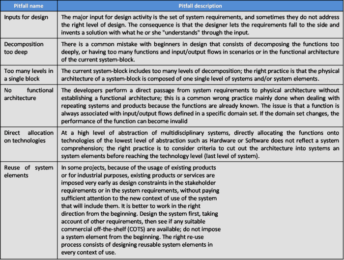
Major pitfalls encountered with Architectural Design are presented in Table 5:
Table 5. Pitfalls with architectural design of systems
Proven practices with architectural design of systems are presented in Table 6:
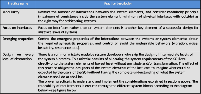
Table 6. Proven practices with architectural design of system
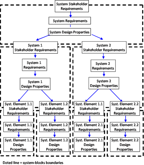
Figure 7 - Requirements Traceability between the system-blocks. (Faisandier, 2011)
References
Please make sure all references are listed alphabetically and are formatted according to the Chicago Manual of Style (15th ed). See the BKCASE Reference Guidance for additional information.
Citations
List all references cited in the article. Note: SEBoK 0.5 uses Chicago Manual of Style (15th ed). See the BKCASE Reference Guidance for additional information.
Alexander, Christopher; Sara Ishikawa, Murray Silverstein, Max Jacobson, Ingrid Fiksdahl-King, Shlomo Angel. 1977. A Pattern Language: Towns, Buildings, Construction. New York: Oxford University Press.
Gamma, Erich; Richard Helm, Ralph Johnson, and John Vlissides. 1995. Design Patterns: Elements of Reusable Object-Oriented Software. Addison-Wesley.
Oliver, D., T. Kelliher, and J. Keegan. 1997. Engineering complex systems with models and objects. New York, NY: McGraw-Hill.
OMG. 2010. OMG Systems Modeling Language – specification - version 1.2 – July 2010 - http://www.omg.org/technology/documents/spec_catalog.htm
Thome, B. 1993. Systems engineering, principles & practice of computer-based systems engineering. New York, NY: Wiley.
ISO/IEC. 2008. Systems and software engineering - system life cycle processes. Geneva, Switzerland: International Organization for Standardization (ISO)/International Electronical Commission (IEC), ISO/IEC 15288:2008 (E).
Primary References
All primary references should be listed in alphabetical order. Remember to identify primary references by creating an internal link using the ‘’’reference title only’’’ (title). Please do not include version numbers in the links.
ANSI/IEEE. 2000. IEEE Recommended Practice for Architectural Description for Software-Intensive Systems. Institute of Electrical and Electronics Engineers, ANSI/IEEE Std 1471:2000.
INCOSE. 2010. INCOSE systems engineering handbook, version 3.2. San Diego, CA, USA: International Council on Systems Engineering (INCOSE), INCOSE-TP-2003-002-03.2.
ISO/IEC. 2008. Systems and software engineering - system life cycle processes. Geneva, Switzerland: International Organization for Standardization (ISO)/International Electronical Commission (IEC), ISO/IEC 15288:2008 (E).
ISO/IEC/IEEE 42010. 2011. Systems and software engineering - Architecture description. Geneva, Switzerland: International Organization for Standardization (ISO)/International Electronical Commission (IEC)/Institute of Electrical and Electronics Engineers (IEEE), ISO/IEC/IEEE FDIS 42010:2011 (E).
Maier, M., and E. Rechtin. 2009. The art of systems architecting. 3rd ed. Boca Raton, FL, USA: CRC Press.
Additional References
All additional references should be listed in alphabetical order.
Faisandier, A. 2011. Engineering and architecting multidisciplinary systems. (expected--not yet published).
Oliver, D., T. Kelliher, and J. Keegan. 1997. Engineering complex systems with models and objects. New York, NY: McGraw-Hill.
Thome, B. 1993. Systems engineering, principles & practice of computer-based systems engineering. New York, NY: Wiley.
