Uploads by Smenck2
Jump to navigation
Jump to search
This special page shows all uploaded files.
| Date | Name | Thumbnail | Size | Description | Versions |
|---|---|---|---|---|---|
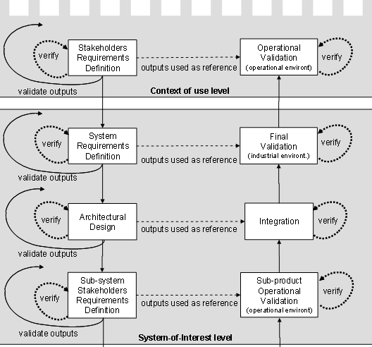
| 18:50, 23 June 2011 | JS Figure 14.png (file) |  |
28 KB | Figure. Verification and Validation Actions in upper levels of system decomposition (SOURCE, YEAR/Permission Pending) | 1 |
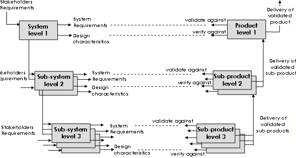
| 18:50, 23 June 2011 | JS Figure 13.png (file) |  |
15 KB | Figure. Verification and Validation level by level (SOURCE, YEAR/Permission Pending) | 1 |
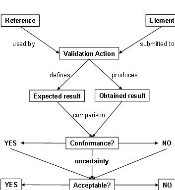
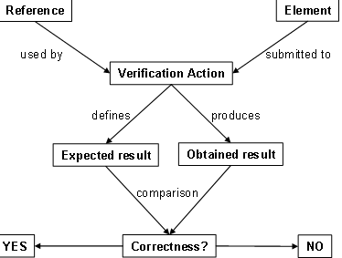
| 18:48, 23 June 2011 | JS Figure 12.png (file) |  |
11 KB | Figure. Definition and usage of a Validation Action (SOURCE, YEAR/Permission Pending) | 1 |
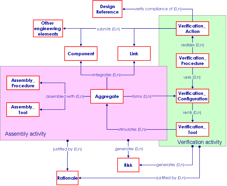
| 18:48, 23 June 2011 | JS Figure 11.png (file) |  |
33 KB | Figure. Verification elements relationships with other engineering elements (SOURCE, YEAR/Permission Pending) | 1 |
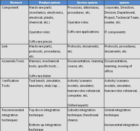
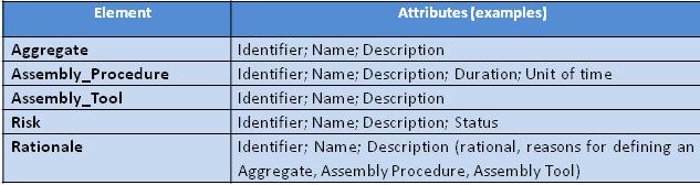
| 18:47, 23 June 2011 | JS Table2.png (file) |  |
20 KB | Table. Main ontology elements as handled within verification (SOURCE, YEAR/Permission Pending) | 1 |
| 18:46, 23 June 2011 | JS Figure 10.png (file) |  |
9 KB | Figure. Definition and usage of a Verification Action (SOURCE, YEAR/Permission Pending) | 1 |
| 18:45, 23 June 2011 | JS Figure 8.png (file) |  |
26 KB | Figure. Integration elements relationships with other engineering elements (SOURCE, YEAR/Permission Pending) | 1 |
| 18:38, 23 June 2011 | JS Table 1.png (file) | 12 KB | Table. Main ontology elements as handled within system integration (SOURCE, YEAR/Permission Pending) | 1 | |
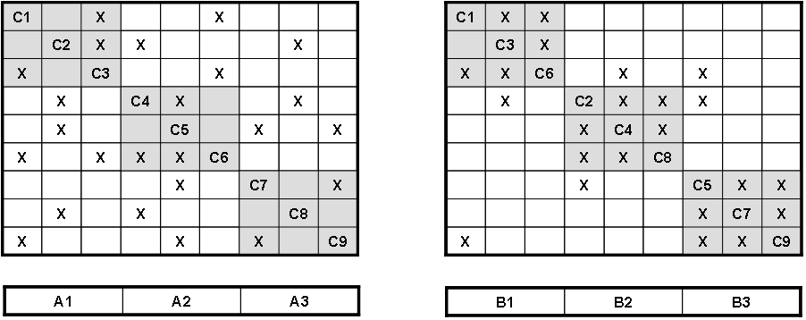
| 18:37, 23 June 2011 | JS Figure 9.png (file) |  |
12 KB | Figure. Initial arrangement of aggregates on the left; final arrangement after reorganization on the right (SOURCE, YEAR/Permission Pending) | 1 |
| 18:32, 23 June 2011 | JS Figure 6.png (file) |  |
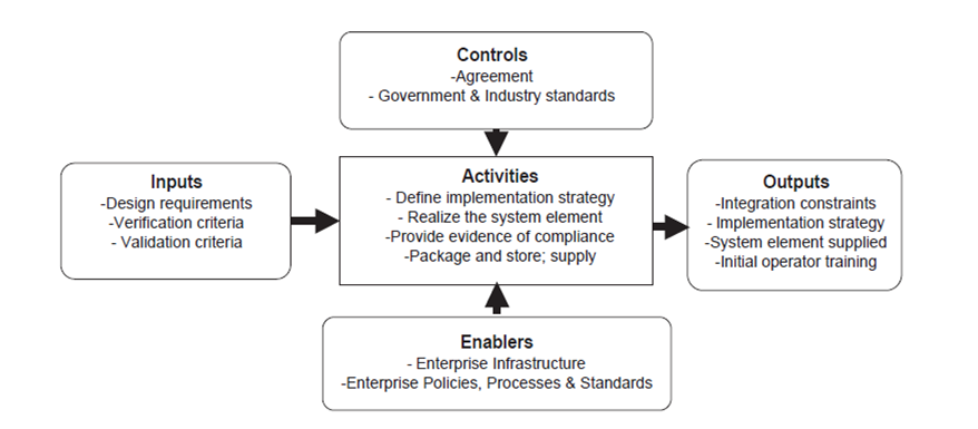
75 KB | Figure. Context diagram for the implementation process (Source: INCOSE, 2010/ Permission Pending) | 1 |
| 18:30, 23 June 2011 | JS Figure 5.png (file) |  |
75 KB | Figure. Context Diagram for the Implementation Process (Source: DAU February 19, 2010/Released) | 1 |
| 18:29, 23 June 2011 | JS Figure 3.png (file) |  |
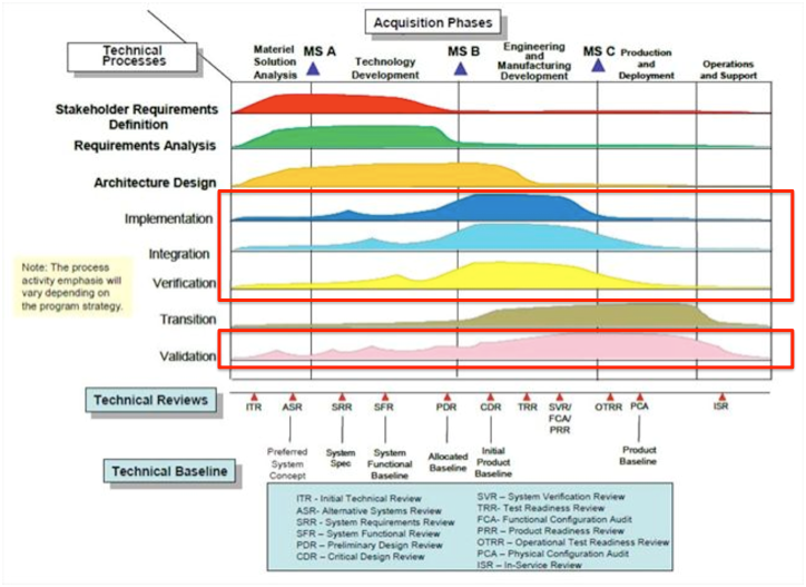
341 KB | Figure. Notional Emphasis of Systems Engineering Technical Processes and the Program Life-cycle Phases (Source: DAU February 19, 2010/Released) | 1 |
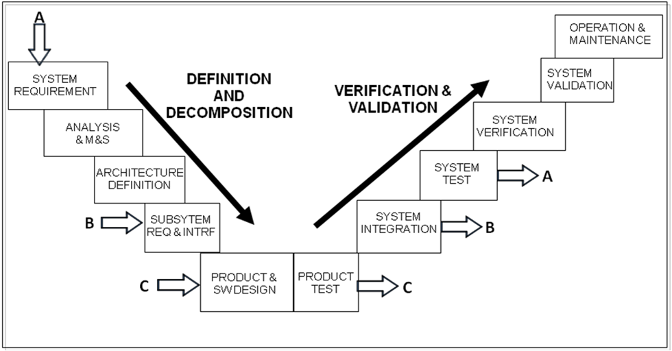
| 18:27, 23 June 2011 | JS Figure 2.png (file) |  |
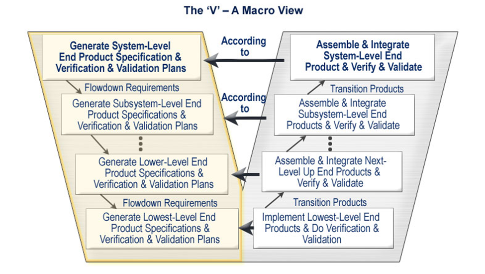
540 KB | Figure. The Vee Activity Diagram (Source: Prosnik, 2010 /Released) | 1 |
| 18:26, 23 June 2011 | JS Figure 1.png (file) |  |
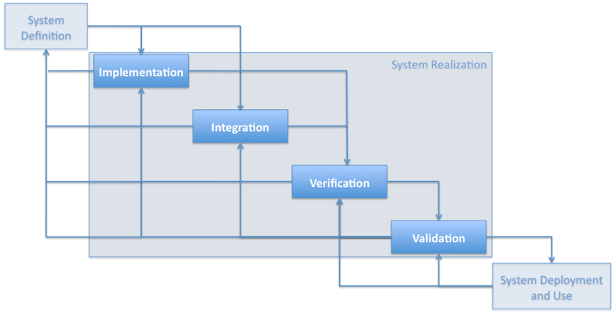
62 KB | Figure. System Realization Context (Figure Developed for BKCASE) | 1 |
| 15:42, 22 June 2011 | 060611 SF System Conept Model-Top Levelnofig10.png (file) |  |
48 KB | Figure. System Concept Model-Top Level ((Source: Oliver, 2003), Permission Pending) | 1 |
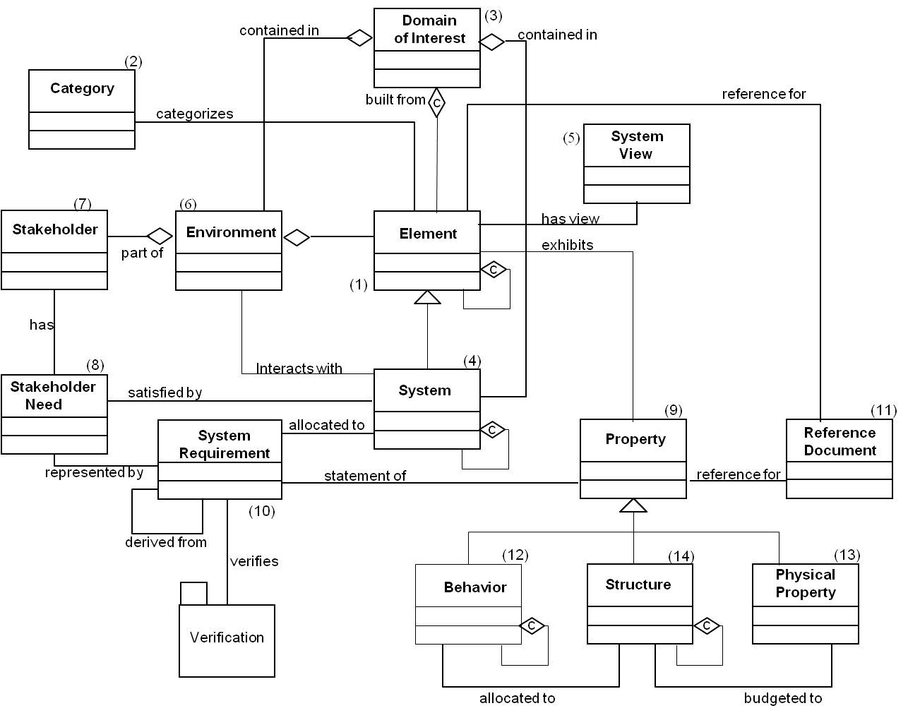
| 15:37, 22 June 2011 | 060611 SF System Conept Model-Top Level.png (file) |  |
49 KB | Figure. System Concept Model-Top Level ((Source: Oliver, 2003), Permission Pending) | 1 |
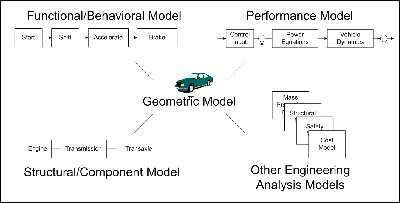
| 15:32, 22 June 2011 | 060611 SF Typical Models.png (file) |  |
51 KB | Figure. Typical Models (Source: NAME, YEAR), Permission Pending) | 1 |
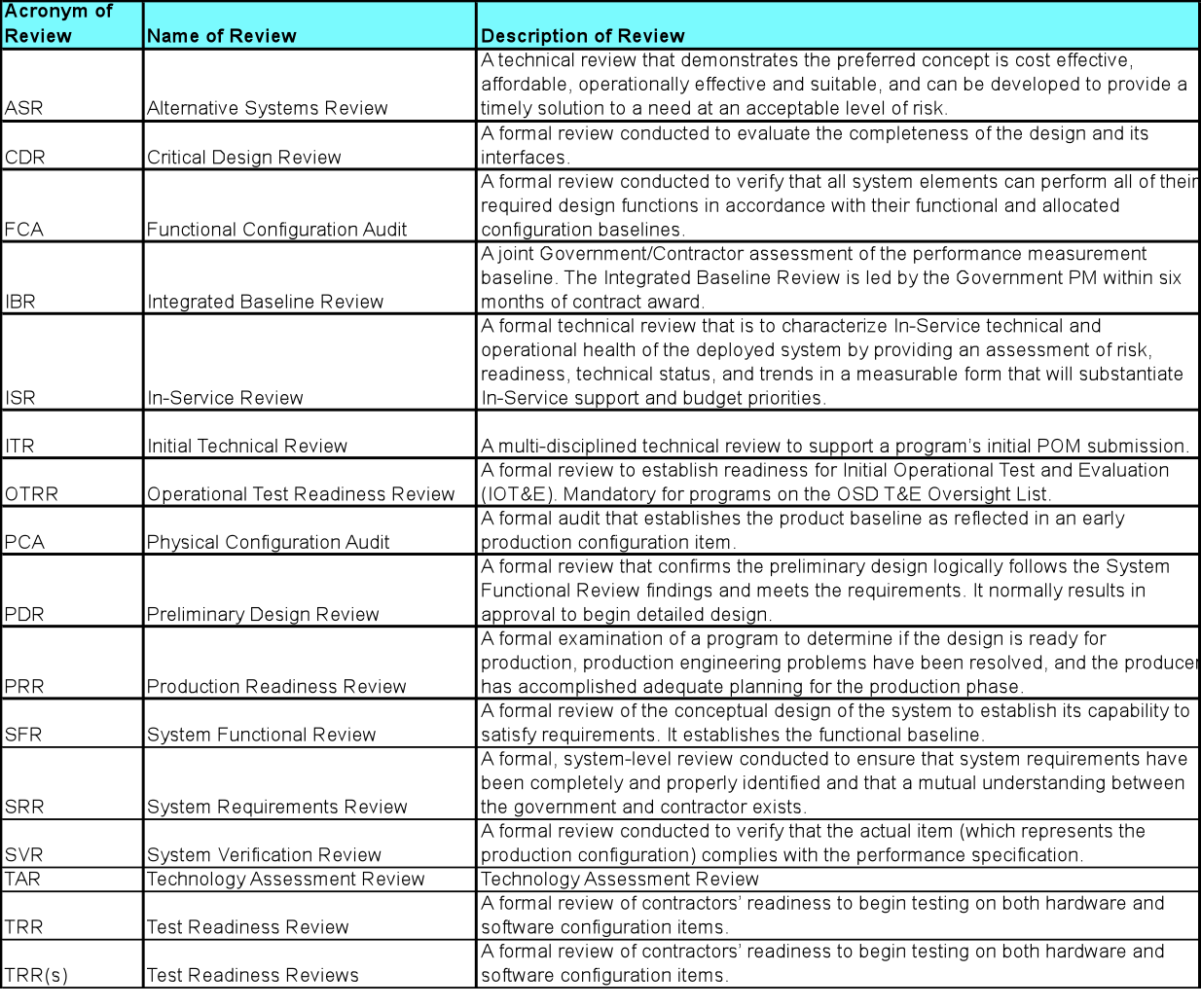
| 20:33, 6 June 2011 | Major technical reviews.png (file) |  |
359 KB | Figure. Major Technical Reviews (Source: NAME, YEAR/Released) | 1 |
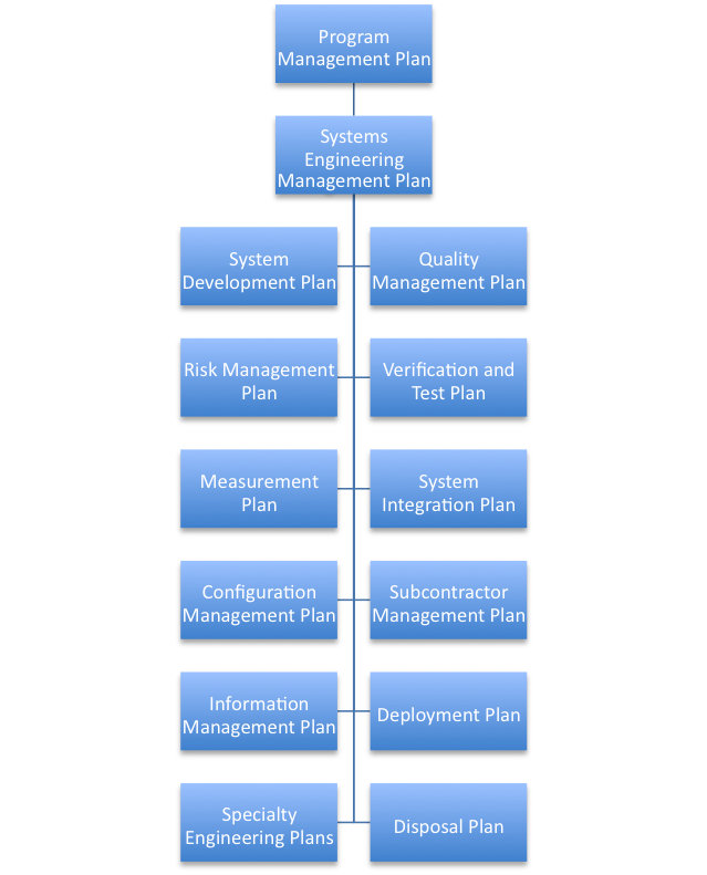
| 20:15, 6 June 2011 | Semp and integrated plans.png (file) |  |
139 KB | Figure. SEMP and Integrated Plans (Figure Developed for BKCASE) | 1 |
| 02:08, 4 June 2011 | ESE-F17.png (file) |  |
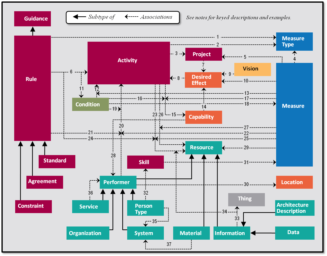
68 KB | Figure. DODAF Conceptual Data Model | 1 |
| 01:37, 4 June 2011 | ESE-F23.png (file) |  |
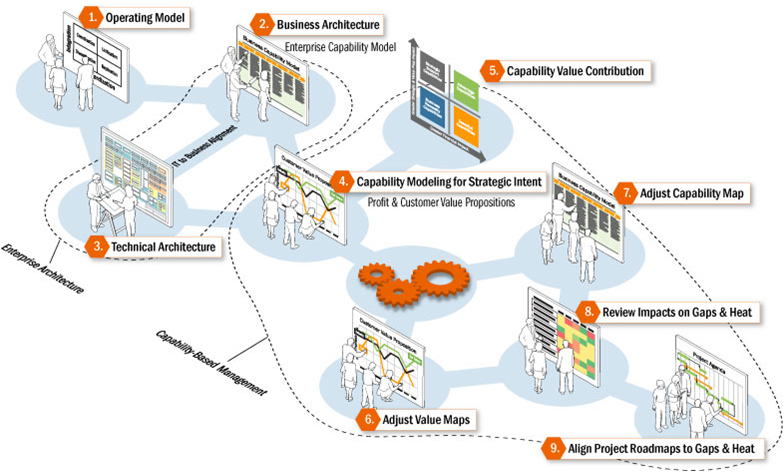
332 KB | Figure. Illustration of Capability Management in the Business Domain | 1 |
| 01:36, 4 June 2011 | ESE-F22.png (file) |  |
37 KB | Figure. Enterprise State Changes Through Work Process Activities | 1 |
| 01:35, 4 June 2011 | ESE-F21.png (file) |  |
52 KB | Figure. Risk & Opportunity at the Enterprise Scale versus the Systems Scale | 1 |
| 01:34, 4 June 2011 | ESE-F20.png (file) |  |
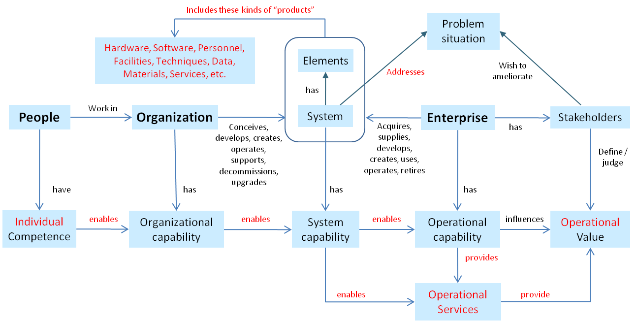
48 KB | Figure. Organizational, System & Operational Capabilities | 1 |
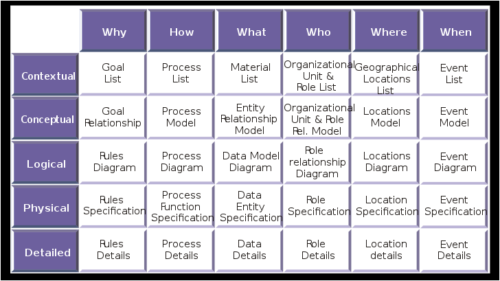
| 01:32, 4 June 2011 | ESE-F19.png (file) |  |
33 KB | Figure. Zachman Framework | 1 |
| 01:32, 4 June 2011 | ESE-F18.png (file) |  |
276 KB | Figure. DODAF Conceptual Data Model | 1 |
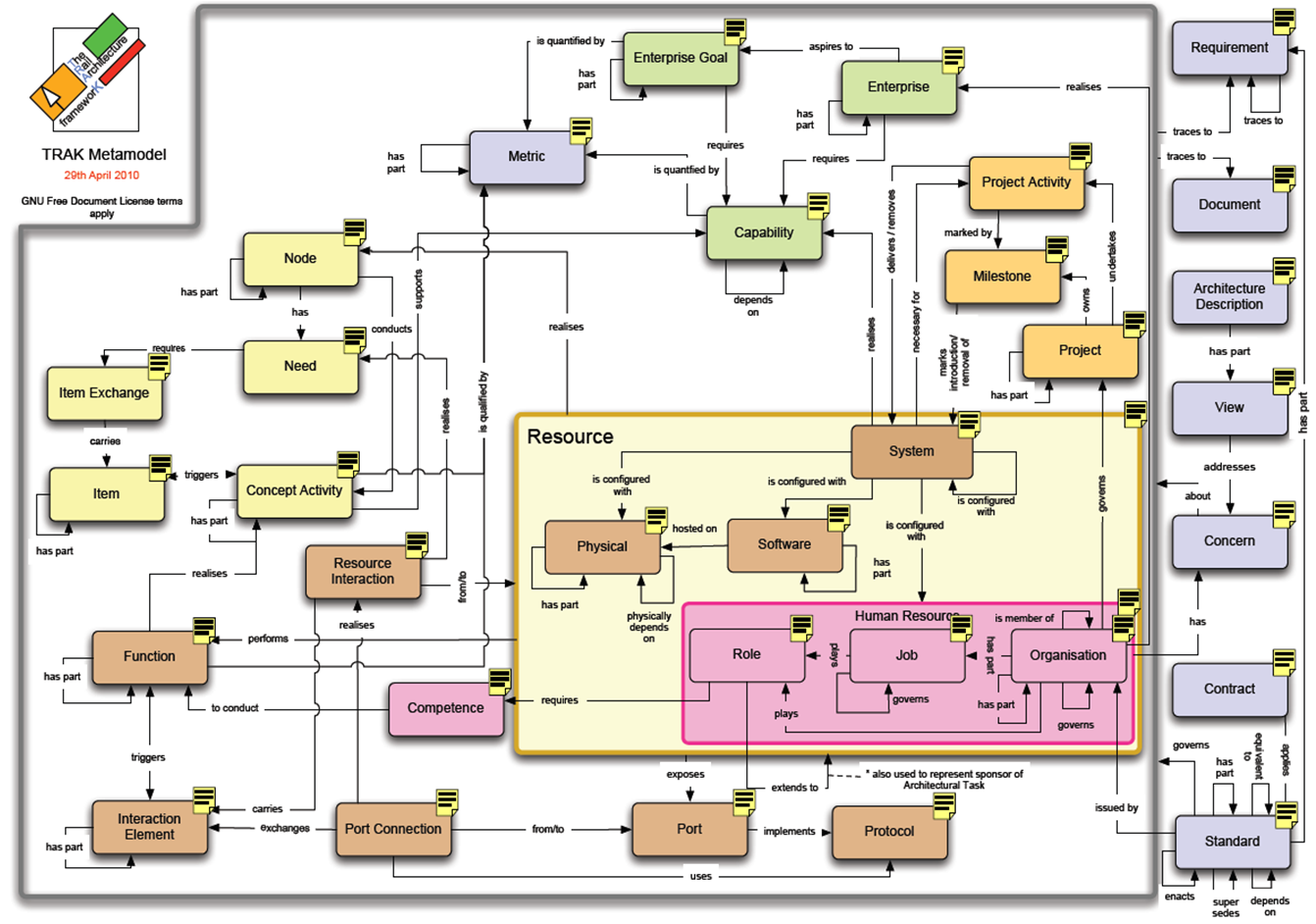
| 01:31, 4 June 2011 | ESE-F16.png (file) |  |
412 KB | Figure. TRAK Metamodel | 1 |
| 01:30, 4 June 2011 | ESE-F15.png (file) |  |
256 KB | Figure. Examples of Enterprise Entities & Relationships | 1 |
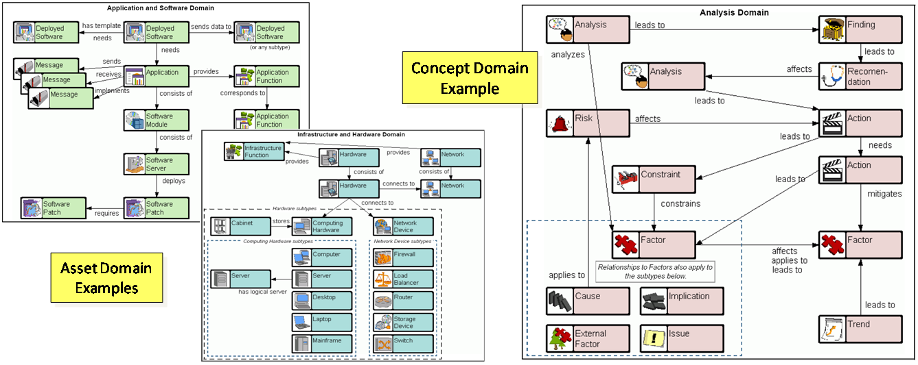
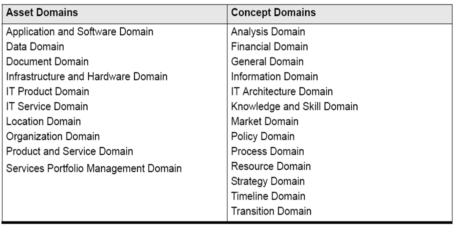
| 01:29, 4 June 2011 | ESE-F14.png (file) |  |
88 KB | Figure. Asset Domain and Concept Domain Categories for Enterprise Entities | 1 |
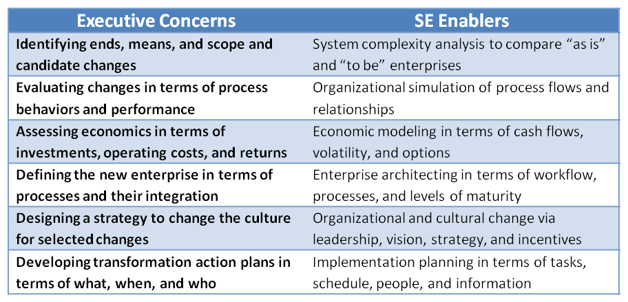
| 19:15, 3 June 2011 | ESE-TA.png (file) |  |
39 KB | Figure Table. Executive Concerns and SE Enablers | 1 |
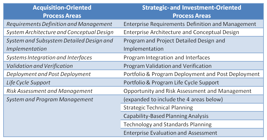
| 19:11, 3 June 2011 | ESE-TB.png (file) |  |
39 KB | Figure Table. Extension of TSE to ESE Process Areas | 1 |
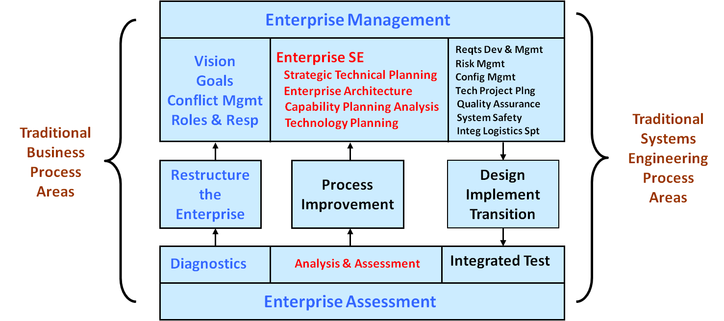
| 19:08, 3 June 2011 | ESE-F13.png (file) |  |
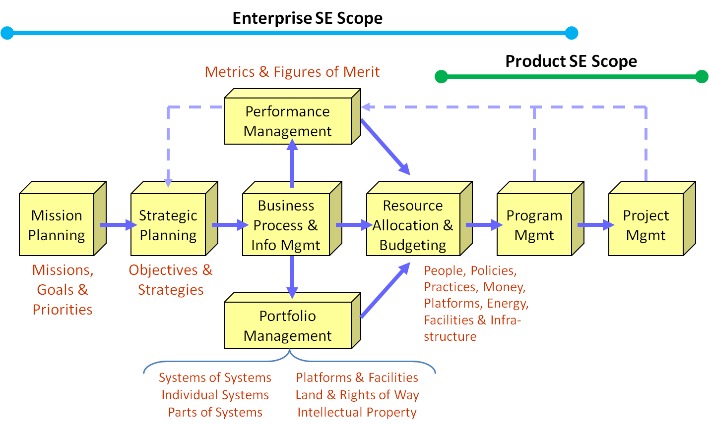
56 KB | Figure. Enterprise SE Process Areas in the Context of the Entire Enterprise | 1 |
| 19:07, 3 June 2011 | ESE-F12.png (file) |  |
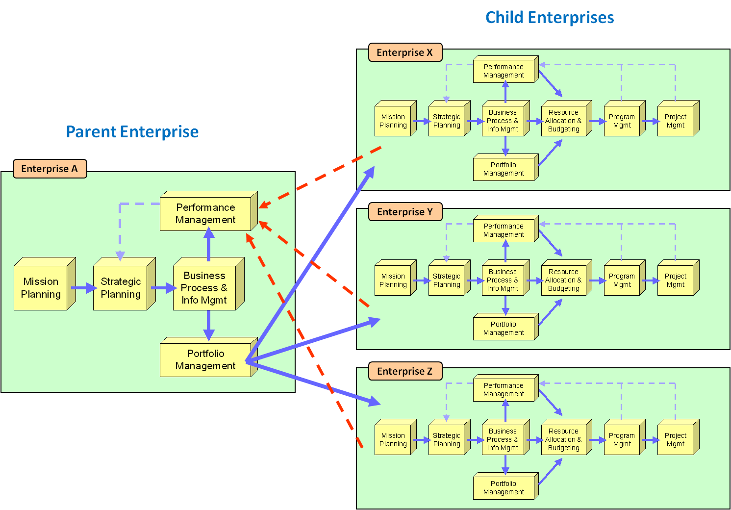
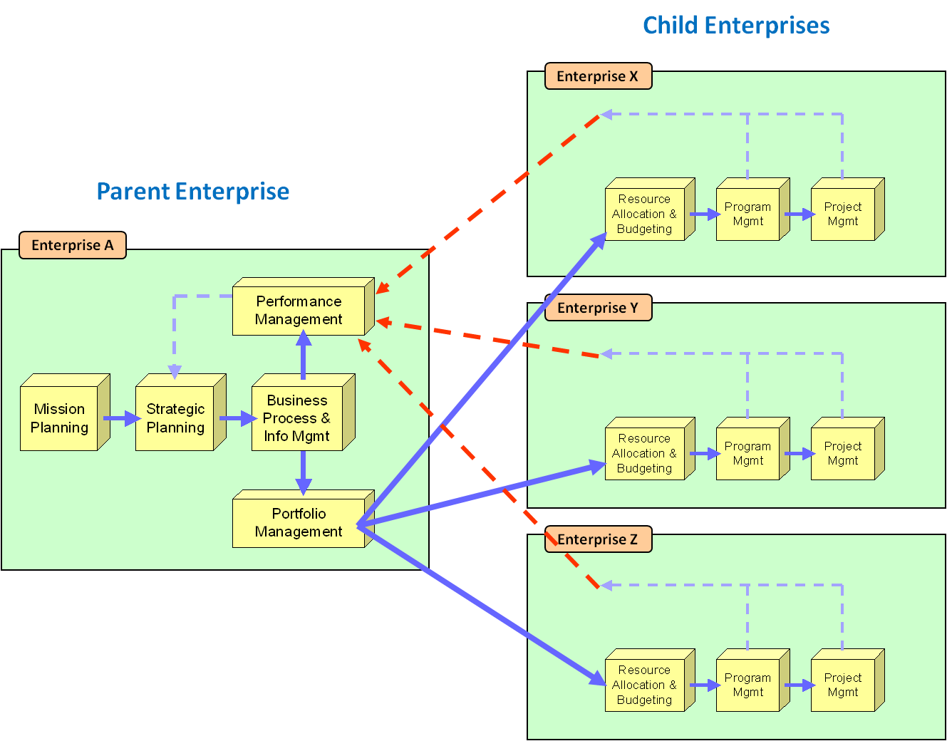
63 KB | Figure. Mission and Strategic Planning at All Levels of Cooperating Enterprises | 1 |
| 19:07, 3 June 2011 | ESE-F11.png (file) |  |
54 KB | Figure. Parent and Child Enterprise Relationships | 1 |
| 19:06, 3 June 2011 | ESE-F10.png (file) |  |
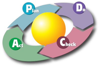
50 KB | Figure. PDCA Cycle | 1 |
| 19:05, 3 June 2011 | ESE-F09.png (file) |  |
59 KB | Figure. Related Business Activities | 1 |
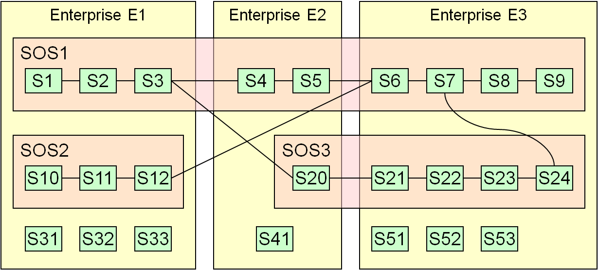
| 19:03, 3 June 2011 | ESE-F08.png (file) |  |
26 KB | Figure. Relationships between an Enterprise and SoSs | 1 |
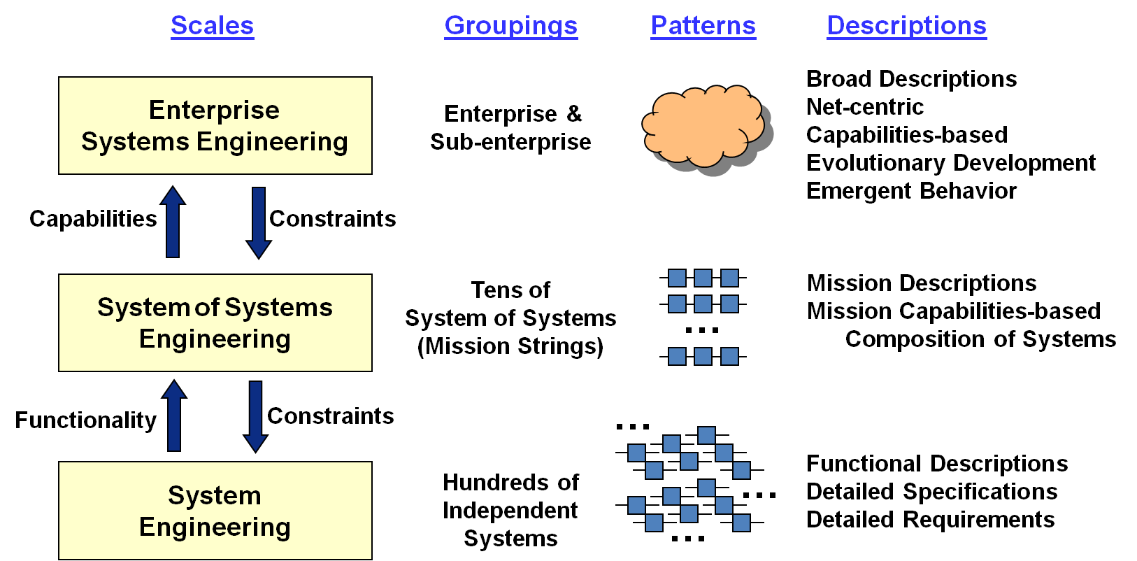
| 19:03, 3 June 2011 | ESE-F07.png (file) |  |
64 KB | Figure. Different Groupings and Patterns Revealed at Different Scales | 1 |
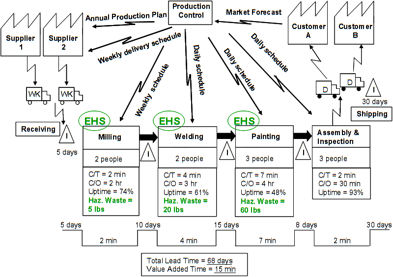
| 19:02, 3 June 2011 | ESE-F06.png (file) |  |
49 KB | Figure. Value Stream Example | 1 |
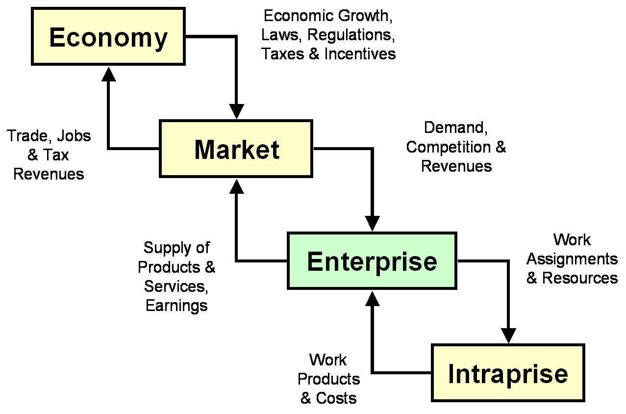
| 19:02, 3 June 2011 | ESE-F05.png (file) |  |
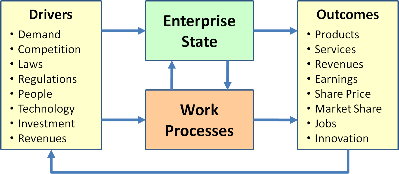
37 KB | Figure. Drivers and Outcomes for the Enterprise | 1 |
| 19:01, 3 June 2011 | ESE-F04.png (file) |  |
21 KB | Figure. Context for Enterprise Transformation | 1 |
| 19:00, 3 June 2011 | ESE-F03.png (file) |  |
176 KB | Figure. Categories of Enterprise Components | 1 |
| 17:35, 3 June 2011 | Fairley Fig 2 Layer 1.png (file) |  |
12 KB | Figure 2. Project Management Subordinate to Systems Engineering (Figure Developed for BKCASE) | 1 |
| 17:34, 3 June 2011 | Fairley Fig 1 (2) Layer 1.png (file) | _Layer_1.png) |
8 KB | Figure 1. SE Team Subordinate to Project Management (Figure Developed for BKCASE) | 1 |
| 16:52, 3 June 2011 | 060111 Fairley Fig 1.png (file) |  |
26 KB | Figure 1. SE Team Subordinate to Project Management (Figure Developed for BKCASE) | 1 |
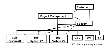
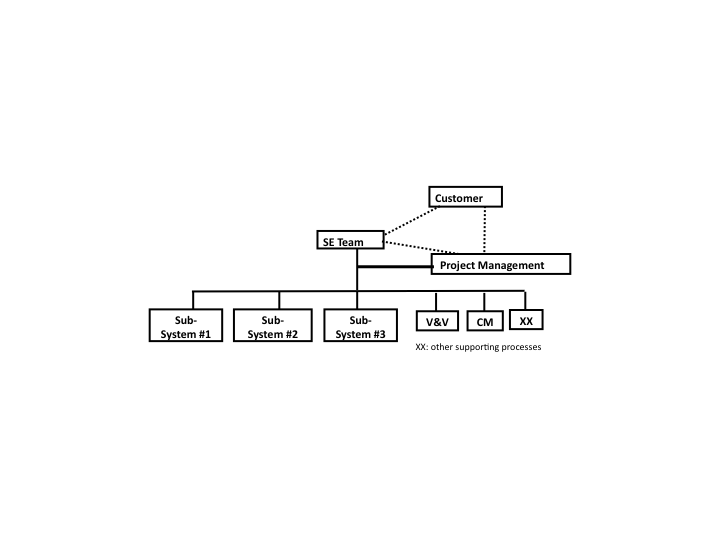
| 16:46, 3 June 2011 | 060111 Fairley Fig 2.png (file) |  |
23 KB | Figure 2. Project Management Subordinate to Systems Engineering (Figure Developed for BKCASE) | 1 |
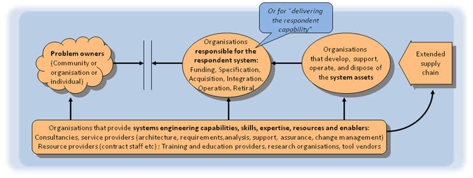
| 14:23, 3 June 2011 | 052911 RB Organisation Coupling Diagram.png (file) |  |
177 KB | Figure. Organisation Coupling Diagram ((Source: Lawson, 2010), Used with Permission) Lawson, H. W. 2010. A journey through the systems landscape. London, UK: College Publications, Kings College. | 1 |
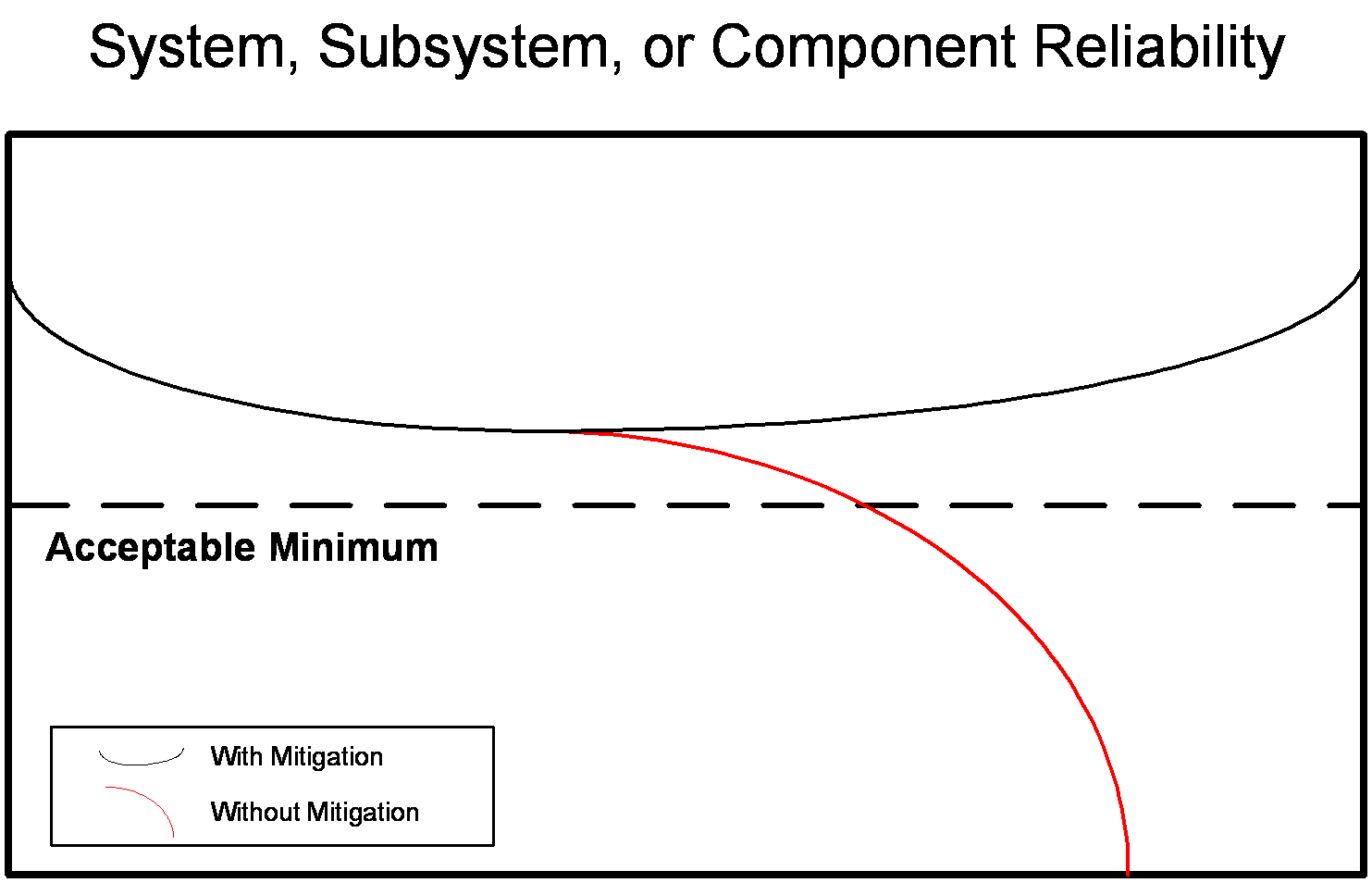
| 19:34, 26 May 2011 | 052611 SJ notional reliability analysis.png (file) |  |
14 KB | Figure. Notional Reliability Analysis (Figure Developed for BKCASE) | 1 |
| 16:09, 24 May 2011 | 052411 BSBW The Vee Model.png (file) |  |
69 KB | Figure. The Vee Model for Modifications at the Three Different Levels (Figure Developed for BKCASE) | 1 |
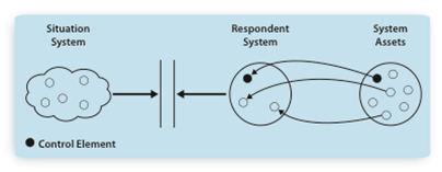
| 19:33, 23 May 2011 | 052311 SJ System Coupling Diagram.png (file) |  |
29 KB | Figure. System Coupling Diagram ((Source: Lawson, 2010), Used with Permission) Lawson, H. W. 2010. A journey through the systems landscape. London, UK: College Publications, Kings College. | 1 |