File list
Jump to navigation
Jump to search
This special page shows all uploaded files.
| Date | Name | Thumbnail | Size | User | Description | Versions |
|---|---|---|---|---|---|---|
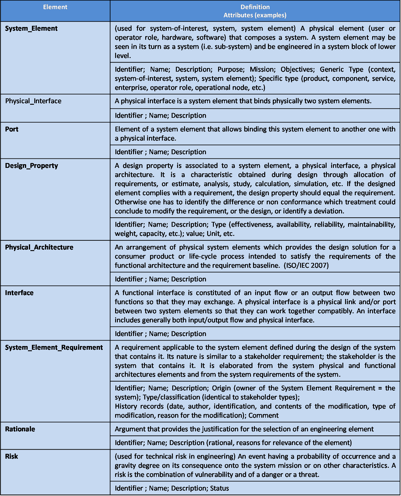
| 02:16, 4 August 2011 | SEBoKv05 KA-SystDef ontology elements Physical Design.png (file) |  |
138 KB | Smenck2 | Table. Main Ontology Elements as Handled within System Physical Design (Figure Developed for BKCASE) | 1 |
| 02:17, 4 August 2011 | SEBoKv05 KA-SystDef Physical Design relationships.png (file) |  |
55 KB | Smenck2 | Figure. Physical Design Elements Relationships with Other Engineering Elements (Source: Faisandier 2011/Used with Permission) © Alain Faisandier-2011 | 1 |
| 02:18, 4 August 2011 | SEBoKv05 KA-SystDef Pitfalls architectural design.png (file) |  |
93 KB | Smenck2 | Table. Pitfalls with Architectural Design of Systems (Figure Developed for BKCASE) | 1 |
| 02:19, 4 August 2011 | SEBoKv05 KA-SystDef practices architectural design.png (file) |  |
56 KB | Smenck2 | Table. Proven Practices with Architectural Design of System (Figure Developed for BKCASE) | 1 |
| 02:19, 4 August 2011 | SEBoKv05 KA-SystDef Progressive Approach for Designing.png (file) |  |
62 KB | Smenck2 | Figure. Progressive Approach for Designing (Source: Faisandier 2011/Used with Permission) © Alain Faisandier-2011 | 1 |
| 02:20, 4 August 2011 | SEBoKv05 KA-SystDef Requirements Traceability between system-blocks.png (file) |  |
38 KB | Smenck2 | Figure. Requirements Traceability Between the System-blocks (Source: Faisandier 2011/Used with Permission) © Alain Faisandier-2011 | 1 |
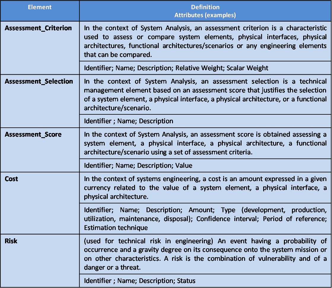
| 02:47, 4 August 2011 | SEBoKv05 KA-SystDef ontology elements System Analysis.png (file) |  |
71 KB | Smenck2 | Table.Main Ontology Elements as Handled within System Analysis (Figure Developed for BKCASE) | 1 |
| 02:48, 4 August 2011 | SEBoKv05 KA-SystDef System Analysis relationships.png (file) |  |
46 KB | Smenck2 | Figure. System Analysis Elements Relationships with Other Engineering Elements (Source: Faisandier 2011/Used with Permission) © Alain Faisandier-2011 | 1 |
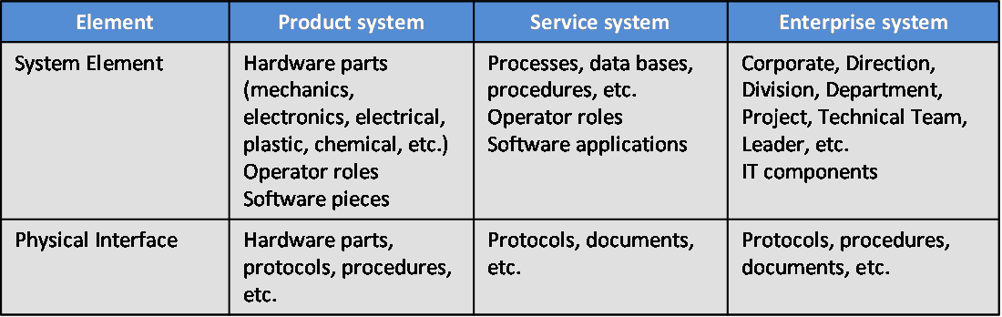
| 02:59, 4 August 2011 | SEBoKv05 KA-SystDef Types of System Elements and Physical Interfaces.png (file) |  |
25 KB | Smenck2 | Table. Types of System Elements and Physical Interfaces (Figure Developed for BKCASE) | 1 |
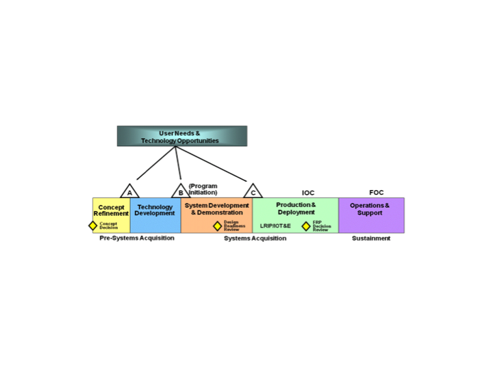
| 03:33, 4 August 2011 | ACQProcessModel.png (file) |  |
87 KB | Smenck2 | Figure. An Acquisition Process Model (Source: DAU, 2001 /Released) | 1 |
| 03:34, 4 August 2011 | RelatingACQtoRFP.png (file) |  |
167 KB | Smenck2 | Figure. Relating Acquisition to Request for Proposal and Technical Attributes (Source: OSD, 2006 /Released) | 1 |
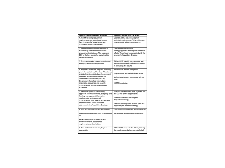
| 03:35, 4 August 2011 | Table 1.png (file) |  |
63 KB | Smenck2 | Table. Offeror’s Systems Engineering and Program Management Roles (Source: OSD, 2006 /Released) | 1 |
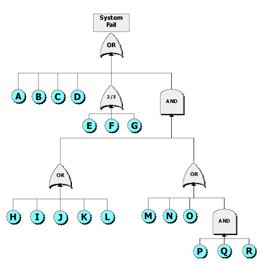
| 03:47, 4 August 2011 | Fault tree.jpg (file) |  |
33 KB | Smenck2 | Figure. Fault Tree (Figure Developed for BKCASE) | 1 |
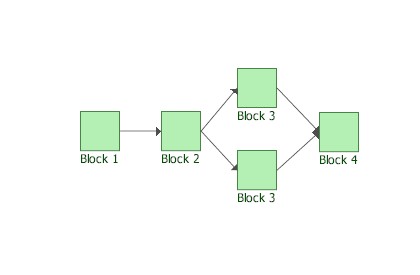
| 03:52, 4 August 2011 | Simple RBD.jpg (file) |  |
9 KB | Smenck2 | Figure. Simple Reliability Block Diagram (Figure Developed for BKCASE) | 1 |
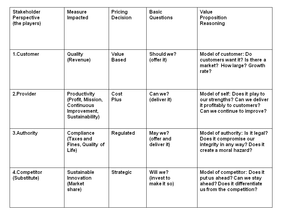
| 21:26, 4 August 2011 | SSE FOS Fig2.png (file) |  |
20 KB | Smenck2 | Figure. Value Calculation From Different Stakeholders’ Perspectives (Source: Spohrer, 2011/ Permission Pending) | 1 |
| 21:26, 4 August 2011 | SSE FOS Fig3.png (file) |  |
34 KB | Smenck2 | Figure. Service Systems Network Diagram (Figure Developed for BKCASE) | 1 |
| 21:27, 4 August 2011 | SSE FOS Fig4.PNG (file) |  |
32 KB | Smenck2 | Figure. Service System Hierarchy (Source: Spohrer, 2011/ Permission Pending) | 1 |
| 21:28, 4 August 2011 | SSE POS Fig1.png (file) |  |
14 KB | Smenck2 | Figure. Service Systems Engineering: Service Evaluation Measures (Source: Tien and Berg, 2003/ Permission Pending) | 1 |
| 21:30, 4 August 2011 | SSE SoSSE Fig2.png (file) |  |
14 KB | Smenck2 | Figure. Service Realization Process: Life Cycle Stages (Source: Figure Developed for BKCASE) | 1 |
| 21:32, 4 August 2011 | SSE SSB Fig1.png (file) |  |
308 KB | Smenck2 | Figure. Service System Context Diagram (Source: Figure Developed for BKCASE) | 1 |
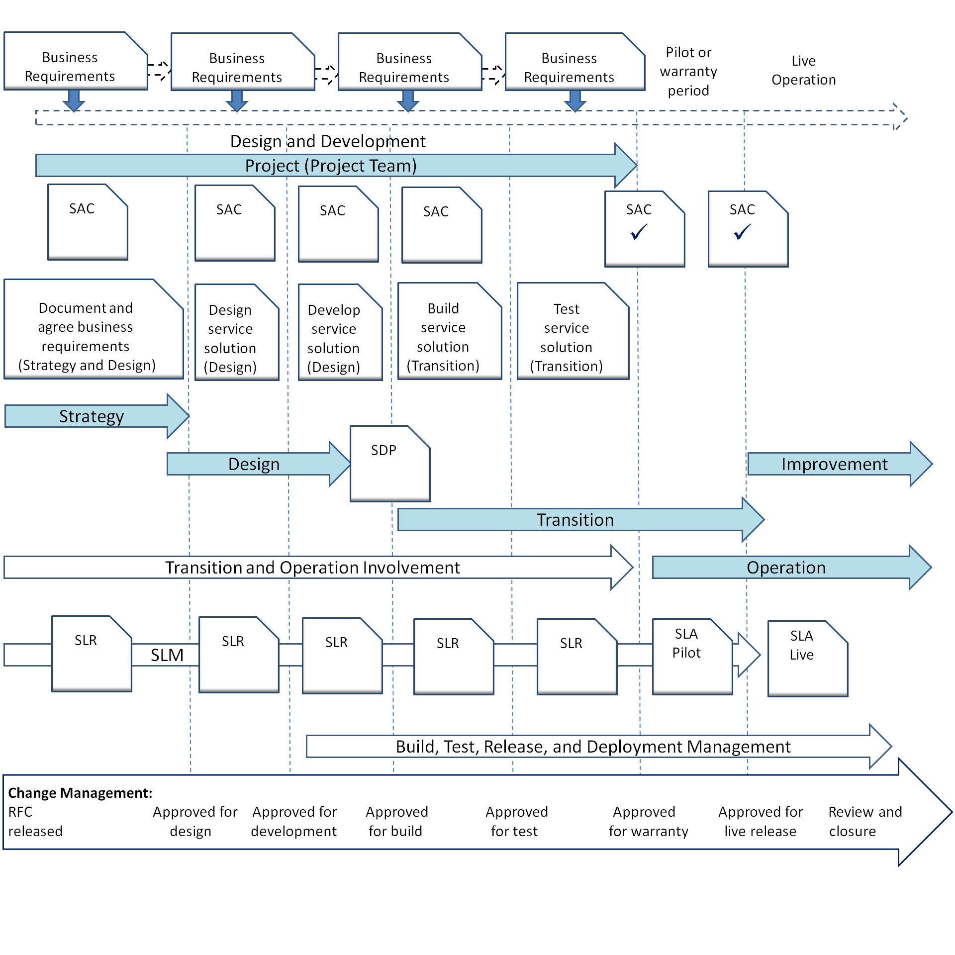
| 21:33, 4 August 2011 | SSE SDP Fig1.png (file) |  |
134 KB | Smenck2 | Figure. Service Lifecycle Stages (Source: Adams, Cartlidge, Hanna, Rance, Sowerby, Windebank, 2009/ Permission Pending) | 1 |
| 21:34, 4 August 2011 | SSE SDP Fig2.png (file) |  |
64 KB | Smenck2 | Figure. Converting Business Requirements into New Services (Source: Adams, Cartlidge, Hanna, Rance, Sowerby, Windebank, 2009/ Permission Pending) | 1 |
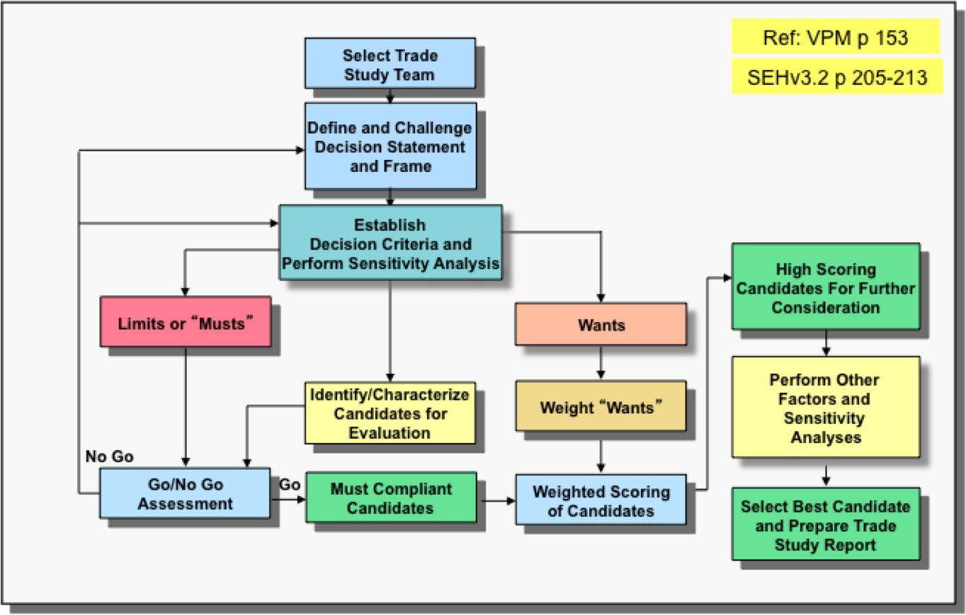
| 02:29, 5 August 2011 | Decision selection flowchart.png (file) |  |
257 KB | Smenck2 | Figure. Decision Selection Flowchart (Source: Forsberg, Mooz, Cotterman, 2005/Permission Pending) | 1 |
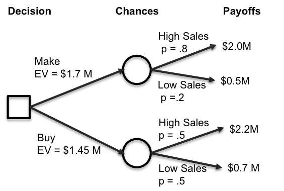
| 02:38, 5 August 2011 | Decision tree example.png (file) |  |
54 KB | Smenck2 | Figure. Decision Tree Example (Source: Figure Developed for BKCASE) | 1 |
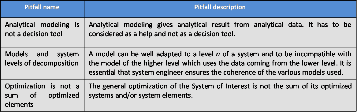
| 03:13, 5 August 2011 | SEBoKv05 KA-SystDef pitfalls System Analysis.png (file) |  |
25 KB | Smenck2 | Table. Pitfalls with System Analysis (Source: Figure Developed for BKCASE) | 1 |
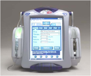
| 03:45, 5 August 2011 | Two channel IV pumps with left channel ill.png (file) |  |
111 KB | Smenck2 | Two Channel IV Pumps with Left Channel Illuminated (Photograph courtesy of Hospira, Inc./Permission Pending) | 1 |
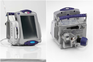
| 04:28, 5 August 2011 | SymBiqTM Pump Industrial Design.png (file) |  |
95 KB | Smenck2 | Symbiq™ Pump Industrial Design (Photograph courtesy of National Academy of Sciences/Permission Pending) | 1 |
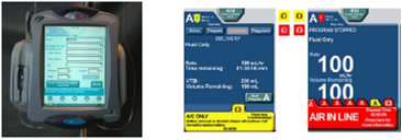
| 04:29, 5 August 2011 | Sample Simulated GUI Screens.png (file) |  |
84 KB | Smenck2 | Sample Simulated GUI Screens (Photograph courtesy of National Academy of Sciences/Permission Pending) | 1 |
| 19:50, 5 August 2011 | SEBoKv05 KA-SystRealiz Definition & performance of V&V Action.png (file) |  |
25 KB | Smenck2 | Figure. Definition and Performance of a Verification and Validation Action(Source: Faisandier 2011/Used with Permission) © Alain Faisandier-2011 | 1 |
| 19:51, 5 August 2011 | SEBoKv05 KA-SystRealiz Implementation relationships.png (file) |  |
17 KB | Smenck2 | Figure. Implementation Elements Relationships with Other Engineering Elements (Source: Faisandier 2011/Used with Permission) © Alain Faisandier-2011 | 1 |
| 19:56, 5 August 2011 | SEBoKv05 KA-SystRealiz integration elements for Product-Service-Enterprise.png (file) |  |
44 KB | Smenck2 | Table. Different Integration Elements for Product, Service, and Enterprise Systems (Source: Figure Developed for BKCASE) | 1 |
| 19:57, 5 August 2011 | SEBoKv05 KA-SystRealiz Integration relationships.png (file) |  |
46 KB | Smenck2 | Figure. Integration Elements Relationships with Other Engineering Elements (Source: Faisandier 2011/Used with Permission) © Alain Faisandier-2011 | 1 |
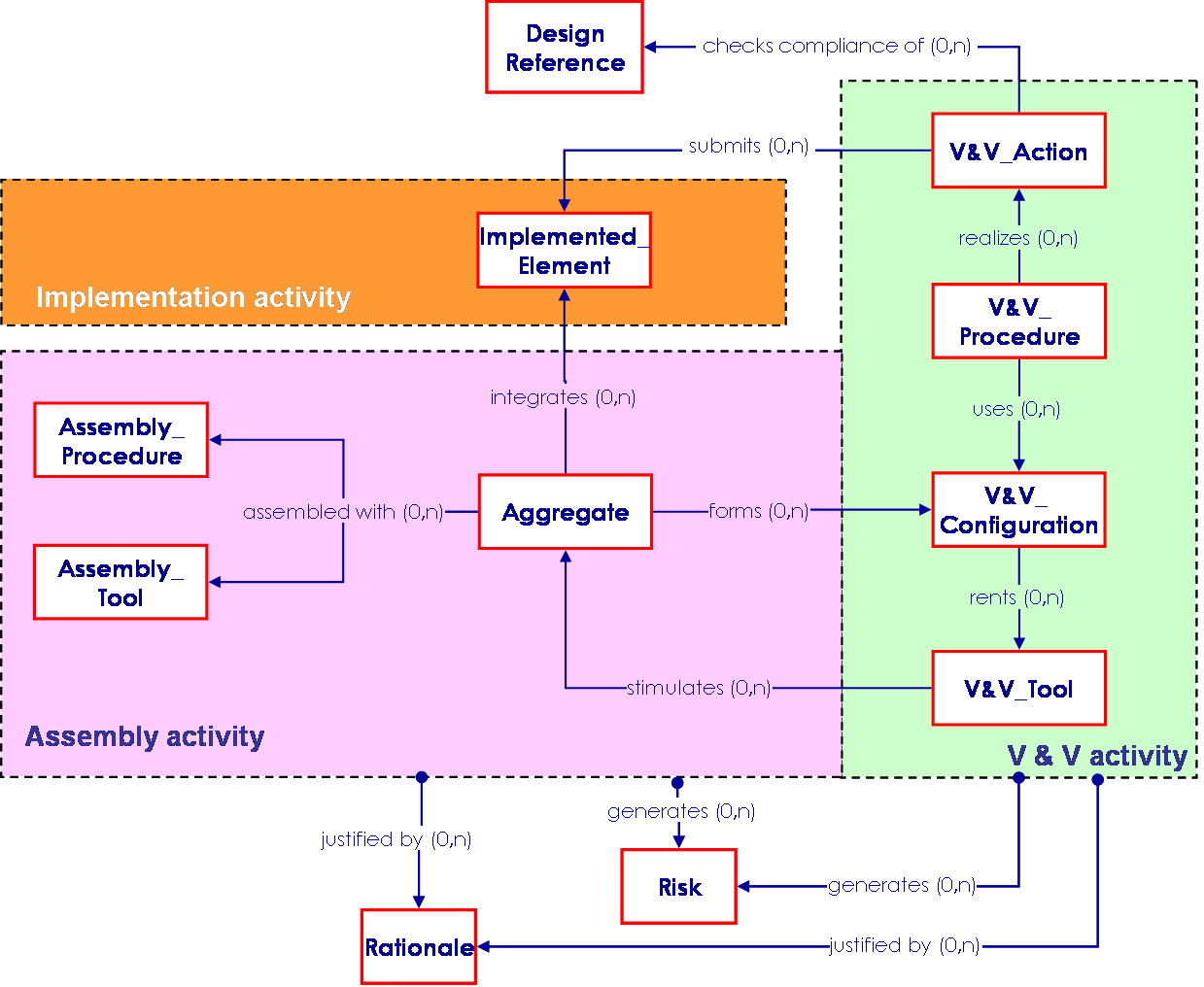
| 19:58, 5 August 2011 | SEBoKv05 KA-SystRealiz simplified view of a meta-data model.png (file) |  |
57 KB | Smenck2 | Figure. A Simplified View of a Meta-data Model for System Realization (Source: Faisandier 2011/Used with Permission) © Alain Faisandier-2011 | 1 |
| 19:59, 5 August 2011 | SEBoKv05 KA-SystRealiz V&V Actions lower levels.png (file) |  |
73 KB | Smenck2 | Figure. Verification and Validation Actions in Lower Levels of System Decomposition (Source: Faisandier 2011/Used with Permission) © Alain Faisandier-2011 | 1 |
| 20:00, 5 August 2011 | SEBoKv05 KA-SystRealiz V&V Actions upper levels.png (file) |  |
74 KB | Smenck2 | Figure. Verification and Validation Actions in Upper Levels of System Decomposition (Source: Faisandier 2011/Used with Permission) © Alain Faisandier-2011 | 1 |
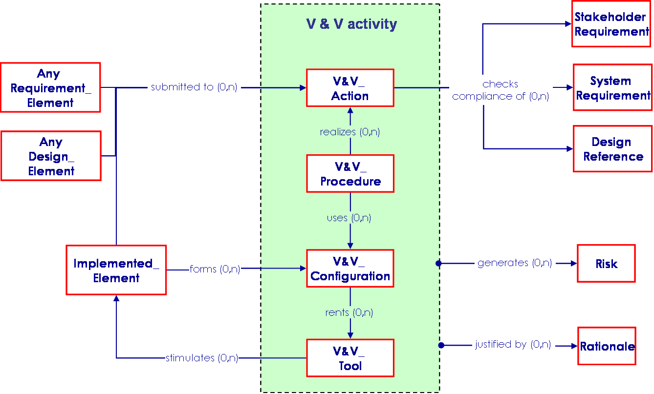
| 20:01, 5 August 2011 | SEBoKv05 KA-SystRealiz V&V relationships.png (file) |  |
38 KB | Smenck2 | Figure. Verification and Validation Elements Relationships with other Engineering Elements (Source: Faisandier 2011/Used with Permission) © Alain Faisandier-2011 | 1 |
| 20:09, 5 August 2011 | SEBoKv05 KA-SystRealiz Verification and Validation level by level.png (file) |  |
48 KB | Smenck2 | Figure. Verification and Validation Level by Level (Source: Faisandier 2011/Used with Permission) © Alain Faisandier-2011 | 1 |
| 20:11, 5 August 2011 | SEBoKv05 KA-SystRealiz ontology V&V.png (file) |  |
65 KB | Smenck2 | Table. Main Ontology Elements as Handled within Verification and Validation (Source: Figure Developed for BKCASE) | 1 |
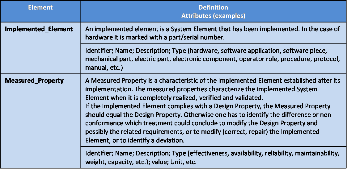
| 20:12, 5 August 2011 | SEBoKv05 KA-SystRealiz ontology within implementation.png (file) |  |
45 KB | Smenck2 | Table. Main Ontology Elements as Handled within System Element Implementation (Source: Figure Developed for BKCASE) | 1 |
| 20:12, 5 August 2011 | SEBoKv05 KA-SystRealiz ontology within System Integration.png (file) |  |
49 KB | Smenck2 | Table. Main Ontology Elements as Handled within System Integration (Source: Figure Developed for BKCASE) | 1 |
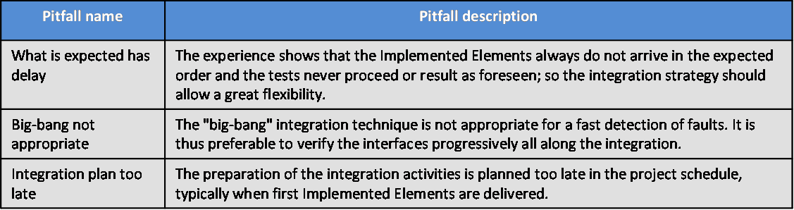
| 20:13, 5 August 2011 | SEBoKv05 KA-SystRealiz pitfalls with System Integration.png (file) | 22 KB | Smenck2 | Table. Major Pitfalls with System Integration (Source: Figure Developed for BKCASE) | 1 | |
| 20:14, 5 August 2011 | SEBoKv05 KA-SystRealiz pitfalls with V&V.png (file) |  |
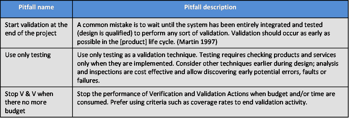
30 KB | Smenck2 | Table. Major Pitfalls with System Verification and Validation (Source: Figure Developed for BKCASE) | 1 |
| 20:15, 5 August 2011 | SEBoKv05 KA-SystRealiz practices with System Integration.png (file) |  |
47 KB | Smenck2 | Table. Proven Practices with System Integration(Source: Figure Developed for BKCASE) | 1 |
| 20:15, 5 August 2011 | SEBoKv05 KA-SystRealiz practices with V&V.png (file) |  |
99 KB | Smenck2 | Table.Proven Practices with System Verification and Validation (Source: Figure Developed for BKCASE) | 1 |
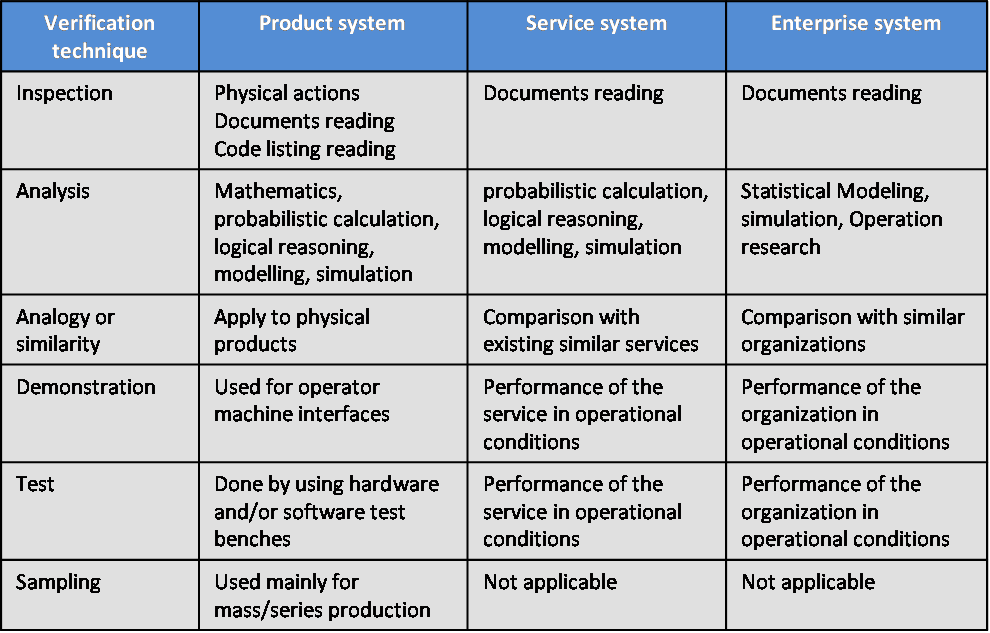
| 20:17, 5 August 2011 | SEBoKv05 KA-SystRealiz Verification techniques and types of system.png (file) |  |
40 KB | Smenck2 | Table. Verification Techniques and Types of System (Source: Figure Developed for BKCASE) | 1 |
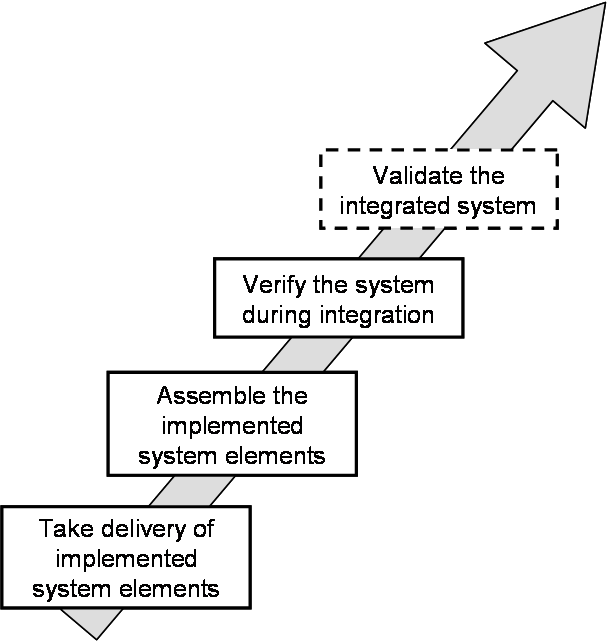
| 20:54, 5 August 2011 | Limits of integration activities.png (file) |  |
18 KB | Smenck2 | Figure. Limits of Integration Activities (Source: Figure Developed for BKCASE) | 1 |
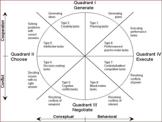
| 20:52, 8 August 2011 | Circumplex Model of Group Tasks.PNG (file) |  |
62 KB | Smenck2 | Figure. Circumplex Model of Group Tasks (Source: McGrath 1984/Permission Pending) | 1 |
| 20:52, 8 August 2011 | Interdependence Examples.png (file) |  |
1.08 MB | Smenck2 | Figure. Interdependence Examples (Source: Forsyth 2010/Permission Pending) | 2 |
| 20:53, 8 August 2011 | Stages of Group Development.PNG (file) |  |
1.55 MB | Smenck2 | Figure. Stages of Group Development (Source: Forsyth 2010/Permission Pending) | 1 |
| 20:57, 8 August 2011 | Circumplex Model of Group Tasks.png (file) |  |
62 KB | Smenck2 | Figure. Circumplex Model of Group Tasks (Source: McGrath 1984/Permission Pending) | 2 |