Uncategorized files
Jump to navigation
Jump to search
Showing below up to 100 results in range #251 to #350.
View (previous 100 | next 100) (20 | 50 | 100 | 250 | 500)
 KF GenericLifeCycleStages.png 468 × 205; 33 KB
 KF GenericStageStructure.png 417 × 316; 57 KB
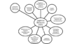
 KF ICSMActivityCategories.png 468 × 515; 97 KB
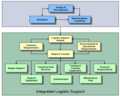
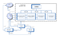
 KF ILSSupportingSystem.png 445 × 232; 38 KB
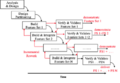
 KF ILSSystemLifeCycle.png 377 × 303; 41 KB
 KF Incremental&EvolDecision.png 450 × 265; 34 KB
 KF Incremental&EvolDevelopment.png 468 × 209; 52 KB
 KF IncrementalBuildCycles.png 433 × 299; 46 KB
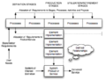
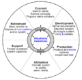
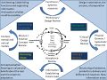
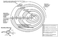 KF IncrementalCommitmentSpiral.png 455 × 296; 54 KB
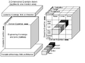
 KF IncrementalDevelopment Multiple.png 468 × 332; 48 KB
 KF IncrementalDevelopment Single.png 468 × 358; 45 KB
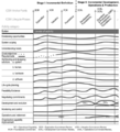
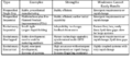
 KF LifeCycleComparisons.png 468 × 433; 94 KB
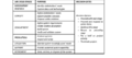
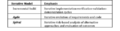
 KF PartitioningCriteria.png 468 × 115; 22 KB
 KF Phase GenericIncremental.png 469 × 363; 64 KB
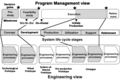 KF ProgramManagement&EngineeringViews.png 358 × 240; 37 KB
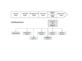
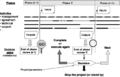 KF SchedulingDevelopment.png 412 × 265; 29 KB
 KF SoftwareDevelopmentEmphasis.png 468 × 122; 22 KB
 KF VeeModel DesignConcept.png 451 × 363; 118 KB
 KF VeeModel ExploratoryResearch.png 441 × 360; 76 KB
 KF VeeModel Left.png 830 × 618; 118 KB
 KF VeeModel Right.png 731 × 571; 107 KB
 LDSE Figure 20200702.gif 2,000 × 1,500; 97 KB
 LM logo Blue notag.200.png 200 × 200; 5 KB
 LM logo Blue notag.png 500 × 121; 2 KB
 Layered and Multi-dimensional in the Engineering Layer.PNG 512 × 384; 18 KB
 Le Ha Phuong.jpg 1,863 × 2,609; 774 KB
 Life-Cycle-Model-Purpose AdaptedfromIEEE Dove.png 733 × 712; 212 KB
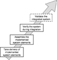 Limits of integration activities.png 609 × 642; 18 KB
 Logo SEBoK 10th.png 1,966 × 987; 431 KB
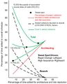
 Loss Driven Systems Engineering Figure 1.png 624 × 383; 15 KB
 MBSE Trends Figure 1.png 1,027 × 533; 22 KB
 MBSE Trends Figure 2.png 761 × 460; 17 KB
 MBSE Trends Figure 3.png 1,473 × 764; 89 KB
 MBSE Trends Figure 4.png 1,008 × 534; 96 KB
 MBSE Trends Figure 5.png 855 × 474; 43 KB
 MBSE Trends Figure 6.png 1,111 × 609; 37 KB
 MBSE Trends Figure 7.png 1,115 × 688; 27 KB
 MBSE Trends Figure 8.png 1,163 × 790; 67 KB
 MITRE Enterprise Systems Engineering Framework.PNG 625 × 384; 147 KB
 Main ontology elements as handled within validation.png 772 × 1,018; 396 KB
 Main ontology elements as handled within verification.png 769 × 1,040; 406 KB
 Major pitfalls with System Validation.png 964 × 667; 190 KB
 Major pitfalls with System Verification.png 964 × 957; 286 KB
 Major technical reviews.png 1,234 × 1,036; 359 KB
 Mapping of tech topics SEBoK with ISO IEC 15288techPro 060612.jpg 761 × 532; 121 KB
 Measurement Process Model-Figure 1.png 960 × 720; 36 KB
 Mediawiki and Caching.pdf ; 54 KB
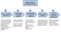 MissionAndCapabilities.png 1,486 × 783; 151 KB
 Missouri-S T PrimaryLogo Apple.png 1,157 × 940; 27 KB
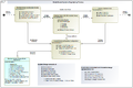 Model-Based System Design Process Part3.png 1,262 × 843; 171 KB
 NASA Image Part 1.png 974 × 663; 122 KB
 Needs-to-requirements-ryan.PNG 960 × 713; 74 KB
 One Spin of the Holon.jpg 960 × 720; 101 KB
 Organizational coupling diagram v2.png 962 × 577; 154 KB
 P1 EconValueSE RiskBalancedfig2 BB.jpg 327 × 403; 21 KB
 P1 Scope and Con SE and Eng Sys Proj LF BB.jpg 1,362 × 845; 145 KB
 P1 Scope and Con SEbok LC and Cont Related Agents BB.jpg 1,205 × 869; 134 KB
 P6 Fig1 The Organizational Continuum KN.jpg 1,166 × 597; 47 KB
- PDFCoverPage P7.pdf ; 9.81 MB
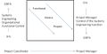
 PM-SE1.jpg 433 × 289; 11 KB
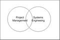
 PM-SE2.jpg 1,009 × 290; 29 KB
 PPI.png 1,200 × 280; 59 KB
 PPI Logo Square.png 1,000 × 764; 34 KB
 PPI Youtube Six-Myths-of-Systems-Engineering final v2.png 2,268 × 1,276; 1.3 MB
 PSE Intro Fig1.png 960 × 720; 55 KB
 PSE Intro Fig2.png 960 × 720; 94 KB
 PSE Intro Fig3.png 960 × 720; 10 KB
 PSE Intro Fig4.png 960 × 720; 13 KB
 PSE PAAS Fig1.png 960 × 720; 80 KB
 PSE PAAS Fig2.png 960 × 720; 36 KB
 PSE PSEB Fig1.png 1,920 × 2,592; 148 KB
 PSE PSEB Fig2.png 960 × 720; 31 KB
 PSE PSEB Tab1.png 960 × 720; 11 KB
 PSE PSEKA Fig1.png 960 × 720; 118 KB
 PSE PSEKA Fig2.png 960 × 720; 12 KB
 PSE PSEKA Fig3.png 960 × 720; 143 KB
 PSE PSEKA Fig4.png 960 × 720; 68 KB
 PSE PSESA Fig1.png 960 × 720; 155 KB
 PSE PSESA Tab1.png 960 × 720; 17 KB
 Part2 Environment 201905.jpg 640 × 518; 67 KB
 Part2 ModifiedCapabilityEngineering 201905.png 1,309 × 882; 122 KB
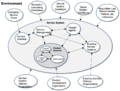 Part2 ServiceSystem 201905.png 1,407 × 1,142; 431 KB
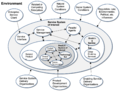 Part2 ServiceSystemofInterest 201905.png 1,466 × 1,111; 521 KB
- Part 2.pdf ; 778 KB
 Part 5 (Organization) Concept maps additions hgs 15 Aug.png 960 × 720; 36 KB
- Part 6.pdf ; 1.1 MB
 Pdf.png 128 × 128; 10 KB
 Picture1.png 1,502 × 1,055; 158 KB
 Picture1 HGS.png 1,502 × 1,112; 323 KB
 Png.jpg 225 × 225; 6 KB
 Proven practices with System Validation.png 763 × 1,050; 362 KB
 Proven practices with System Verification.png 964 × 703; 208 KB
 QQBKCASE Sect 2.5 Fig 6C.png 2,000 × 1,500; 62 KB
 Recursion of processes on layers 060612.jpg 1,158 × 849; 90 KB
 Recursive Instantiation of Def Process AF 071112.png 1,343 × 827; 225 KB
 References Image.png 1,071 × 143; 21 KB
 RelatingACQtoRFP.png 720 × 540; 167 KB
 RelatingACQtoRFP NoWhiteS.png 721 × 542; 373 KB
 Relating ACQ to Req for Prop and Tech Atts p6.jpg 662 × 469; 929 KB


_Concept_maps_additions_hgs_15_Aug.png)


