|
|
| (88 intermediate revisions by 15 users not shown) |
| Line 1: |
Line 1: |
| − | In order to illustrate concepts described in the [[SEBoK 0.5 Outline|Systems Engineering Body of Knowledge (SEBoK)]], this vignette deals with [[Systems Engineering (glossary)|systems engineering (SE) (glossary)]] concepts and guidelines applied to the development of the Standard Korean Light Transit System (SKLTS). The project itself is not for commercial operation, but for providing the reliable technical platform of commercial systems planned later.
| + | ---- |
| − | | + | '''''Lead Authors:''''' ''Heidi Davidz, Alice Squires, Chuck Calvano'', '''''Contributing Authors:''''' ''Richard Turner'' |
| − | In Korea, local authorities have been interested in light transit to resolve their transportation problems. They with the central government decided to develop the standard platform of Korean light transit systems during the 7-year period between 1999 and 2005. Then local authorities introduced the SKLTS to their precincts. Successful examples include the Inchun Airport Line and the Seoul 9th Subway Line. | + | ---- |
| − | | + | This example was created as a SE example directly for the SEBoK. It deals with {{Term|Systems Engineering (glossary)|systems engineering}} (SE) concepts and guidelines applied to the development of the Standard Korean Light Transit System (SKLTS). In Korea, local authorities had historically been interested in light transit to help resolve their transportation problems. The SKLTS was a joint effort between local authorities and the central government. It was built to provide a standard platform on which any local authority could construct its own light transit system. The issues of [[Stakeholder Needs and Requirements|stakeholder requirements]], [[System Safety|safety]], and [[System Reliability, Availability, and Maintainability|reliability, availability, and maintainability]] were critical to the success of this system. |
| − | Design of the transit system was developed with the emphasis on [[Reliability, Availability, and Maintainability|reliability, availability, maintainability, and safety]] (RAMS). The project organization consists of representatives from various institutions including the central government, local authorities, and companies involved. The objective of the project is the [[System Verification and Validation|verification and validation]] (V&V) of the SKLTS by using a test railway.
| |
| − | | |
| − | Following ISO/IEC 15288 (Korea Technology and Standard Institute, 2009), the [[Life Cycle Models|project lifecycle]] of the SKLTS consists of 7 phases from concept studies to operation. In each phase, we identify issues related to RAMS. Requirement analysis identifies RAMS issues of various stakeholders. The function analysis and allocation is based on scenario-based simulation with SE tools including RDD-100. SE activities of the project guarantee that the whole system can achieve the desired RAMS level.
| |
| − | | |
| − | ==Vignette Description==
| |
| − | The SKLTS provides the standard platform, based on which any local authority can construct its light transit system. Hence, its design should accommodate various requirements from not only local authorities but also the central government. The project has proceeded with the schedule as follows;
| |
| − | | |
| − | *1999: concept studies and development
| |
| − | *2000: pre-design
| |
| − | *2001: design
| |
| − | *2002~4: production and test
| |
| − | *2005: performance evaluation
| |
| − | *2006~ : subsequent proliferation
| |
| − | | |
| − | The elements of the SKLTS can be classified into 4 groups as shown in Fig. 1: trains, signal systems, electric and machinery (E&M), and structures. Trains and vehicles are supposed to be automatically operated without human operators. Operation systems including their interfaces are based on digital signal and communication. SE-based design activities focus on RAMS, and should be integrated to project management activities during all phases.
| |
| − | | |
| − | [[File:ChoeKimFigure1.png|600px|Elements of the Unmanned Light Transit System]] | |
| − | | |
| − | Figure 1. Subsystems of the SKLTS (Ahn, 2005)
| |
| − | * CCU: Central Control Unit, TTC: Total Traffic Control, ATP: Automatic Train Protection, ATO: Automatic Train Operation, PSD: Platform Screen Door
| |
| − | | |
| − | The [[Life Cycle Models|project lifecycle]] for the SKLTS is summarized as Fig. 2. It consists of 7 phases: concept studies, concept development, preliminary design, design, system production and test, performance evaluation, and operation/maintenance/close-out (OMC) – see Choi (2007) and Chung et al. (2010) for details. Each phase except the production and test phase is complete with the evaluation and decision point (EDP), which is depicted as a colored circle in the figure.
| |
| − | | |
| − | [[File:ChoeKimFigure2.png|600px|System Engineering Processes for the URTS]] | |
| − | | |
| − | Figure 2. 7 phases of the KLTS development
| |
| − | | |
| − | The phase of concept studies is to identify possible stakeholders and their preliminary requirements, and to research the current status of technologies required. The EDP at the end of this phase is based on user requirement documents and concept study reports. Experts outside the project team also participate in the review process.
| |
| − | | |
| − | The phase of concept development is to determine stakeholders and their requirements in a more systematic and comprehensive way. The major outputs include complete requirements documents and reports.
| |
| − | | |
| − | The major objective of the preliminary design phase is to provide the request for proposal (RFP), which emphasizes SE implementation. If the system is required to be divided into several subsystems, their interrelationships and interfaces are examined during this phase. Then an RFP is provided for each subsystem.
| |
| − | | |
| − | The design phase begins with establishing the baseline. Every user requirements should be met by design. This correspondence is managed during the whole lifecycle. At the EDP, the results of this phase are evaluated by pre-design reports, requirement analysis documents, project baseline, and final design.
| |
| − | | |
| − | The phase of system production and test consists of system development, production, test, and operation training. This phase does not have any formal EDP, which is scheduled at the end of the performance evaluation phase. Instead, various check points are scheduled during production and test processes.
| |
| − | | |
| − | The performance evaluation phase focuses on the validation of user requirements and the verification of design. The validation process is based on requirements documents, baseline plans, and V&V results of system elements. This phase also includes activities to prepare commercial operation. Activities of the OMC phase are supported by the results of previous phases. The third-party evaluation team will monitor them.
| |
| − | | |
| − | ===SE Framework of the SKLTS===
| |
| − | | |
| − | SE activities during the SKLTS development focus on RAMS as summarized in Tab. 1. In the phases for concept studies and concept development, SE activities identify all the requirements for the system to define the target performance including the objectives of reliability, availability, and maintainability (RAM). Design criteria and system functions are also established. Planning activities in this phase include various tests and evaluations scheduled in the future. The basic layout of rails and command rooms is proposed. Finally, we define interface management procedures and relationships between requirements and systems. For RAMS engineering, we also establish various plans and criteria such as RAM plans, safety plans, service availability, and so on.
| |
| − | | |
| − | [[File:ChoeKimTABLE1.png|600px|The SE Framework of the SKLTS]]
| |
| − | | |
| − | Table 1. The SE framework of the SKLTS (Ahn, 2005)
| |
| − | | |
| − | In the pre-design phase, the basic architecture of the system is determined for safety planning, RAM planning, and operation scenarios. Interfaces among subsystems are carefully defined as well as management procedures for contractors and legal regulations. The function analysis deals with timeline, accuracy of stop points and trip times. Pre-design activities include the specifications of major system elements such as signal systems, trains, interface and so on. For RAMS engineering, safety scenarios are defined, and the hazard and risk analysis is performed.
| |
| − | | |
| − | During the phases for design and performance evaluation, the hazard log and RAM analysis are performed to meet safety requirements for every subsystems. The specifications of alarm systems and stations are also defined. V&V procedures are determined for performance evaluation. Then the testing team is established to specify test procedures.
| |
| − | | |
| − | Initial operation is performed only after the system is accepted and operators are properly certified. During test operation, RAM performance is continuously monitored. The FRACAS is operated to gather accident and failure data. Its results will help the maintenance system and procedures. Continuous improvement is required when the system is in normal operation.
| |
| − | | |
| − | ===Project Organization===
| |
| − | The [[Enabling Systems Engineering|project organization]] of the SKLTS is shown in Fig. 3. The Ministry of Construction and Transportation is the major sponsor, and the Korea Railroad Research Institute (KRRI) is responsible for project management. The steering committee consists of representatives of the ministry, research institutions, project members, and audit agency. According to the classification scheme shown in Fig. 1, the project organization consists of 5 parts such as engineering, train systems, power supply systems, signal & control systems, and structures. Each part has main contractors shown in the parentheses, and consists of 3 ~ 12 companies.
| |
| − | | |
| − | [[File:ChoeKimFigure3.png|600px|SKLTS Project Organization]]
| |
| − | | |
| − | Figure 3. SKLTS project organization (Han, 2006)
| |
| − | | |
| − | ===Requirements Analysis===
| |
| − | [[System Requirements|Requirements]] of the SKLTS are classified into mission requirements and system requirements by using an SE tool, RDD-100. Mission requirements can be summarized as follows:
| |
| − | | |
| − | * To have the transportation capability of 5,000~20,000 passengers/one way
| |
| − | * To be based on existing urban railway systems and technologies
| |
| − | * To evaluate performance by test railway
| |
| − | * To effectively apply SE principles and guidelines
| |
| − | * To provide LR service safer than legacy rail services
| |
| − | * To be efficient under the domestic environment
| |
| − | | |
| − | These requirements are defined in the first phase. In the following phases, they are refined especially with the consideration of environment, function, safety, v&v, regulations, and technologies. System requirements are classified into 4 groups as follows:
| |
| − | | |
| − | * I/O requirements: system input, system output, external interface, function
| |
| − | * Technology requirements: technology, “-ilities”, cost, time
| |
| − | * Trade-off requirements: cost, performance, cost vs. performance
| |
| − | * V&V requirements: v&v, certification
| |
| − | | |
| − | ===Function Analysis and Allocation===
| |
| − | For the [[Architectural Design|function analysis]], RDD-100 provides a scenario-based simulation module called as DVF (Dynamic Verification Facility). It is able to run scenario-based simulation so that the precedence relationships of functions and messages among them can be identified. In other words, we use scenarios to evaluate the dynamic behavior of the system. For example, the functions of trains are simulated by scenarios as follows:
| |
| − | | |
| − | *Pre-test scenario
| |
| − | *Normal operation scenario
| |
| − | *Emergency operation scenario
| |
| − | *Rescue operation scenario
| |
| − | | |
| − | A scenario example of the lowest level by RDD-100 is given in Fig. 4. Using the results of the function analysis, functions are allocated to the elements in the systems architecture (Lee, 2002). Fig. 5 shows an example of function and requirement allocation.
| |
| | | | |
| − | [[File:ChoeKimFigure4.png|600px|Scenario for self inspection]]
| + | ==Description== |
| − |
| + | The elements of the SKLTS were classified into four groups (as shown in Figure 1): trains, signal systems, electric and machinery (E&M) systems, and structures. Trains and vehicles were to be automatically operated, without need for human operators. Operation systems and their interfaces were based on digital signals and communications. For SKLTS, SE-based design activities focused on reliability, availability, maintainability, and safety (RAMS), and were integrated into project management (PM) activities during all phases. |
| − | Figure 4. An example of behavior scenarios by RDD-100 (Han and Lee, 2005)
| |
| | | | |
| − | [[File:ChoeKimFigure5.png|600px|Function and requirement allocation]] | + | [[File:ChoeKimFigure1.png|thumb|center|600px|'''Figure 1. Subsystems of the SKLTS (Ahn, 2005).''' (Notes: CCU: Central Control Unit; TTC: Total Traffic Control; ATP: Automatic Train Protection; ATO: Automatic Train Operation; PSD: Platform Screen Door) Reprinted with permission of ''Journal of the Korean Society for Railway''. All other rights are reserved by the copyright owner.]] |
| | | | |
| − | Figure 5. An example of function and requirement allocation (Han and Lee, 2005) | + | The [[Life Cycle Models|project life cycle]] for the SKLTS is summarized in Figure 2. It consisted of 7 phases: concept studies, concept development, preliminary design, design, system production and testing, performance evaluation, and operation/maintenance/close-out (OMC) - please see (Choi 2007) and (Chung et al. 2010) for further details. These phases, with the exception of the production and test phases, are completed through an evaluation and decision point (EDP) ({{Term|Milestone (glossary)|milestone}}), depicted as a colored circle in Figure 2. These EDPs correspond to common life cycle artifacts such as requests for proposal (RFPs), proposals, preliminary design reviews (PDRs), and critical design reviews (CDRs). |
| | | | |
| − | ===Design===
| + | [[File:ChoeKimFigure2.png|thumb|center|600px|'''Figure 2. 7 phases of the SKLTS development (Ahn 2005).''' Reprinted with permission of the ''Journal of the Korean Society for Railway''. All other rights are reserved by the copyright owner.]] |
| | | | |
| − | For integrated and consistent [[System Definition|design]], the design/construction interface manual (D/CIM) is defined, and applied to every details of design (Bombardier, 2005). The D/CIM specifies the detail of trains, railway, and structures.
| + | During the SKLTS development, SE activities were focused on RAMS as summarized in Table 1. |
| | | | |
| − | ===Verification and Validation===
| + | {| |
| − | The safety and reliability of the SKLTS are evaluated on test railway which is constructed by the standard specifications. These issues are very critical to the success of the SKLTS, because it is an automatically-driven system. In addition to our own data, experiences and data in countries with unmanned LTS are very helpful for tests and specifications related to safety and reliability. For ensuring safety, the safe operation guidelines are enforced. The guidelines show how to recover and operate the system under each type of accidents and emergencies. | + | |+'''Table 1. The SE Framework of the SKLTS (Ahn 2005).''' Reprinted with permission of the ''Journal of the Korean Society for Railway''. All other rights are reserved by the copyright owner. |
| | + | !Phases |
| | + | !Safety |
| | + | !Reliability |
| | + | !Function |
| | + | !Performance |
| | + | |- |
| | + | |Concept studies |
| | + | | |
| | + | *Requirements analysis |
| | + | | |
| | + | *Identifying RAM conditions |
| | + | *RAM allocation |
| | + | | |
| | + | *System configuration |
| | + | *Interface management |
| | + | | |
| | + | *Performance simulation |
| | + | |- |
| | + | |Concept development & pre-design |
| | + | | |
| | + | *Safety planning |
| | + | *Defining safety procedures & levels |
| | + | | |
| | + | *RAM planning |
| | + | *Initial availability analysis |
| | + | | |
| | + | *Defining scenarios and alarm procedure |
| | + | *Pre-designing command rooms |
| | + | | |
| | + | *Interface analysis |
| | + | |- |
| | + | |Design |
| | + | | |
| | + | *Hazard log |
| | + | *Safety case analysis |
| | + | *Risk analysis |
| | + | | |
| | + | *Reporting RAM analysis |
| | + | *RAM analysis of auxiliary systems |
| | + | | |
| | + | *Defining alarm systems |
| | + | *Train analysis |
| | + | *Functionality analysis of stations |
| | + | | |
| | + | *Interface analysis |
| | + | |- |
| | + | |Performance evaluation |
| | + | | |
| | + | *Safety test planning & testing |
| | + | | |
| | + | *Verification and Validation (V&V) RAM |
| | + | *Maintainability test |
| | + | | |
| | + | *System test planning and testing |
| | + | | |
| | + | *Performance test planning & testing |
| | + | |- |
| | + | |Initial Operation |
| | + | | |
| | + | *System acceptance |
| | + | *Driver certification |
| | + | | |
| | + | *RAM monitoring |
| | + | *FRACAS<nowiki>*</nowiki> |
| | + | | |
| | + | *Analyzing systems |
| | + | *Identifying improvement points |
| | + | | |
| | + | *Performance monitoring |
| | + | |} |
| | | | |
| − | ===Specialty Engineering - RAMS===
| + | <nowiki>*</nowiki>FRACAS: Failure Reporting & Corrective Action System |
| − | RAMS is one of major interest. Hence, various methods are applied for achieving the RAMS objectives. Some of them are the RAMS requirements analysis, safety and RAMS planning, systems scenarios, construction risk analysis, and RAMS analysis reports.
| |
| | | | |
| − | First, for the comprehensive RAMS requirements analysis, every quantitative and qualitative requirement for RAMS is identified. Examples are as follows;
| + | In the "concept studies" and "concept development" phases, requirements included the RAMS objectives. Planning activities in this phase included the scheduling of various tests and evaluations to be conducted after system design. The basic layout of rails and command rooms was also proposed. Finally, it was during this phase that interface management procedures and relationships between requirements and systems were defined. For RAMS engineering, it was also important to establish associated plans and criteria (e.g., RAM plans, safety plans, service availability, etc.). |
| | | | |
| − | * Target level of reliability and availability
| + | During the pre-design phase, the basic architecture of the system was determined for safety planning, RAMS planning, and operational scenarios. Interfaces among subsystems, management procedures for contractors and legal regulations were defined. were defined as well as management procedures for contractors and legal regulations. The functional analysis dealt with timeline, accuracy of stop points, and trip times. Pre-design activities also included the specifications of major system elements such as signal systems, trains, and interfaces. For RAMS engineering, safety scenarios were defined, and the hazard and risk analyses were performed. |
| − | * Requirements analysis for subsystems to ensure those of the whole system
| |
| − | * Tolerance limits of reliability tests
| |
| − | * Engineering guidelines for the maintainability of the system
| |
| − | * Safety criteria
| |
| − | * Risk limits of the system including passengers, operators, etc.
| |
| − | * Allocation of the safety level of each subsystem
| |
| − | * Guidelines for accidents and emergencies
| |
| | | | |
| − | Both qualitative and quantitative requirements for safety are defined. Those requirements are analyzed not only for the railway system but also for facilities and structures, such as ATC, SCADA, command rooms, platform sliding doors, and so on. The requirements analysis for safety leads to the safety plan. It defines safety-related works and processes of each phase, and also the safety management organization. It also includes the safety plans of contractors. Managing factors related to RAM, the RAM plan defines activities and procedures necessary in each phase of the lifecycle. The plan is revised with the results and schedules of phases.
| + | During the design and performance evaluation phases, hazard log and RAMS analyses were performed to ensure that each subsystem met safety requirements. The specifications of alarm systems and stations were also defined. In addition, V&V and test procedures were determined for performance evaluation. During the design phase, a design/construction interface manual (D/CIM) was developed and applied to ensure integrated and consistent [[System Definition|design]]. (Bombardier, 2005.) |
| | | | |
| − | System scenarios are important documents for evaluating the functions required for unmanned operation. For making scenarios, we assume the 3 types of operation modes (normal operation, fall-back operation, and emergency operation) and the 2 types of facilities (stations and depots). Hence 6 scenarios are evaluated in the end. Each scenario describes actions, procedures, timelines, and signals necessary for the situation.
| + | Because SKLTS was designed as an automatically-driven system, RAMS issues were critical to its success. The safety and reliability of the SKLTS were evaluated on a test railway that was constructed to standard specifications. Data was gathered from existing Korean light rail systems, as well as the light rail systems from other countries, to support V&V activities. |
| | | | |
| − | The construction risk analysis specifically focuses on construction and civil works. Risk factors of construction are identified from the early phase, and their list is properly maintained. For example, the analysis is re-checked whenever an engineering change is required. Each risk identified is resolved and managed by engineering design teams. The analysis also suggests the roles and responsibilities of risk management personnel and the schedules of activities required.
| + | Various methods were applied for achieving the RAMS objectives, including RAMS requirements analysis, safety and RAMS planning, utilization of systems scenarios, and construction risk analysis. |
| | | | |
| − | The RAM analysis report shows if the whole system may achieve the desired RAM level by analyzing RAM data of subsystems. First, the RAM factors of each subsystem are identified, and their effects on the whole system are evaluated. Proper actions are taken to resolve an issue, if required. Second, each subsystem is verified to achieve the reliability objectives desired. Finally, the cost and time for overall RAM actives are estimated.
| + | Initial operation of SKLTS was allowed only after the system was formally accepted and operators were properly certified. During test operation, RAMS performance was continuously monitored and system scenarios were used successfully to evaluate the dynamic behavior of the system. A failure reporting and corrective action system (FRACAS) was used to gather accident and failure data. Continuous improvement when the system is in normal operation was identified as a requirement; the results from the FRACAS will be used to support improvement of the system, maintenance, and improvement of procedures. |
| | | | |
| | ==Summary== | | ==Summary== |
| − | This case deals with systems engineering (SE) concepts and guidelines applied for the development project of the standard Korean light transit system (SKLTS). In Korea, local authorities have been interested in light transit systems to resolve their transportation problems. They with the central government developed the standard type of Korean light railway systems during the 7-year period between 1999 and 2005. Then local authorities introduced the SKLTS to their precincts with some modifications. Successful examples include the Inchun Airport Line and the Seoul 9th Subway Line.
| + | Korean local authorities have successfully introduced the SKLTS to their precincts with some modifications. Successful examples include the Inchun Airport Line and the Seoul 9th Subway Line. One lesson learned that was identified was that requirement analysis, especially in the first few phases, should have been more complete. |
| | | | |
| − | The SKLTS is initiated to provide its flexible basis. Hence, in addition to the typical design of the railway system, we need to focus on reliability, availability, maintainability, and safety (RAMS) with comprehensive level and interface management. The project organization consists of representatives from various institutions including the central government, local authorities, and companies involved.
| + | ==References== |
| | + | ===Works Cited=== |
| | + | Ahn, S.H. 2005. “Systems Engineering Applied to the Construction of Unmanned Light Rail Transit Systems.” ''Journal of the Korean Society for Railway.'' 8(2): 41-49. |
| | | | |
| − | SE works and activities are supported by an SE tool, RDD-100. It is capable of scenario-base simulation for the function analysis. Design activities are integrated mostly by the use of the design/construction interface manual (D/CIM). We apply various methods to achieve the objectives related to RAMS. Some of them are the RAMS requirements analysis, safety and RAMS planning, systems scenarios, construction risk analysis, and RAMS analysis reports. These methods enable us to effectively manage project activities, and to achieve the objective desired.
| + | Bombardier. 2005. ''Design/Construction Interface Manual''. Montréal, Québec, Canada: Bombardier. |
| | | | |
| − | It was found that the SE tool itself is not critical to the success of the project, and that the requirement analysis especially in the first few phases should be more complete. Finally, this article does not have the details of SE activities for interface management, configuration management, EMI/EMC management, and noise/vibration management.
| + | Choi, Y.C. 2007. "Systems eEngineering aApplication mModel for the nNational R&D pProject: Focusing on the rRailway sSystems." Ph.D. dissertation, Ajou University, Suwon, South Korea, 2007. |
| | | | |
| − | ==References==
| + | Chung, S. Y., S.G. Lee, D.W. Lee, and S.T. Jeon. 2010. “A sStudy on tThe aApplication mModel of sSystems eEngineering to Aadvance the bBusiness of the Light Rail Transit (LRT).” Proceedings on the Autumn Conference of the Korean Society for Railway, p. 24-30. |
| − | ===Citations===
| |
| − | * Ahn, S. H., “Systems engineering applied to the construction of unmanned light rail transit systems”, Journal of the Korean Society for Railway, Vol. 8, No. 2, pp. 41-49, 2005.
| |
| − | * Bombardier, Design/Construction Interface Manual, 2005.
| |
| − | * Choi, Y. C., Systems Engineering Application Model for the National R&D Project: Focusing on the Railway Systems, Ph.D. dissertation, Ajou Univ., 2007.
| |
| − | * Chung, S. Y., Lee, S. G., Lee, D. W. and Jeon, S. T., “A study on the application model of systems engineering to advance the business of the Light Rail Transit (LRT)”, Proceedings on the Autumn Conference of the Korean Society for Railway, pp. 24-30. 2010.
| |
| − | * Han, S. Y. and Lee, A. H., System Engineering for the Technology Development Program of Light Transit Systems, internal research report, the Korea Railroad Research Institute, 2005.
| |
| − | * Korea Technology and Standard Institute, KSX ISO/IEC 15288: Life Cycle Processes of IT Systems Based on Systems and Software Engineering, research report, The Korea Technology and Standard Institute, 2009.
| |
| − | * Lee, W. D., “A study on the top-level functional analysis for the automated guideway transit by system engineering tools”, Proceedings on Autumn Conference of the Korean Society for Railway, pp. 202-207, 2002.
| |
| | | | |
| | ===Primary References=== | | ===Primary References=== |
| | None. | | None. |
| | + | |
| | ===Additional References=== | | ===Additional References=== |
| − | None.
| + | Han, S.Y. and A.H. Lee. 2005. ''System Engineering for The Technology Development Program of Light Transit Systems: Internal Research Report.'' Gyeonggi-do, South Korea: Korea Railroad Research Institute. |
| − | ----
| |
| − | ====Article Discussion====
| |
| − | [[{{TALKPAGENAME}}|[Go to discussion page]]]
| |
| − | <center>[[FAA AAS Vignette|<- Previous Article]] | [[Vignettes|Parent Article]] | Last Page [[Main_Page|(Return to Home)]] </center>
| |
| − | 5
| |
| − | Usage quibble: "7-year period between 1999 and 2005" -- the period BETWEEN 1999 and 2005 would be 2000, 2001, 2002, 2003 and 2004 -- or 5 years. The 7-year period is the "period of 1999 to 2005".
| |
| | | | |
| − | Figure 1 does not seem to show up as a figure.
| + | Korean Agency for Technology and Standards. 2009. ''KSX ISO/IEC 15288: Life Cycle Processes of IT Systems Based on Systems and Software Engineering, Research Report.'' Gyeonggi-do, South Korea: Korean Agency for Technology and Standards. |
| | | | |
| − | "integrated TO project management activities" should, I think, be "integrated WITH project management activies".
| + | Lee, W.D. 2002. “A study on the top-level functional analysis for the automated guideway transit by system engineering tools.” Proceedings of the Autumn Conference of the Korean Society for Railway, p. 202-207. |
| | | | |
| − | "The project lifecycle for the SKLTS is summarized as Figure 2." WHERE is Figure 2?
| + | ---- |
| − | | + | <center>[[UK West Coast Route Modernisation Project|< Previous Article]] | [[Matrix of Implementation Examples|Parent Article]] | [[Northwest Hydro System|Next Article >]] </center> |
| − | "Figure 2. also does not appear as a figure.
| |
| − | | |
| − | "Every user requirements should be met by design..." "requirement" should be singular.
| |
| − | | |
| − | There are references within the body to "Tab 1" and "Table 1". WHERE are these? It appears that the entire paragraph following the words "Table 1" was supposed to be in table form. But it isn't -- all the words are run together as though it was regular prose.
| |
| − | | |
| − | Figure 3 missing as well. Appears to be a formatting issue with figures and tables. ALL FIGURES seem missing or somehow not formatted.
| |
| − | | |
| − | Descriptive: OK
| |
| − | | |
| − | balance: OK
| |
| − | | |
| − | Scope: OK
| |
| − | | |
| − | Writing: Some issues -- apparently it is largely formatting for the WIKI that is the problem.
| |
| − | | |
| − | Citations: OK
| |
| − | | |
| − | References: OK
| |
| − | | |
| − | Glossary: OK
| |
| − | | |
| − | Cross-Linkages: OK
| |
| − | | |
| − | Maturity: Good, except for formatting issues with figures, tables.
| |
| − | | |
| − | (Davidz, 08/22) New text from Dr. Choe entered today, tried to correct first person references, updated hyperlinks, still need figures and tables
| |
| | | | |
| − | ==Signatures==
| + | <center>'''SEBoK v. 2.9, released 20 November 2023'''</center> |
| − | [[Category: Part 7]][[Category:Topic]][[Category:Case Study]]
| |
| | | | |
| − | --[[User:Hdavidz|Hdavidz]] 15:05, 15 August 2011 (UTC)
| + | [[Category: Part 7]][[Category:Example]] |
Lead Authors: Heidi Davidz, Alice Squires, Chuck Calvano, Contributing Authors: Richard Turner
This example was created as a SE example directly for the SEBoK. It deals with systems engineeringsystems engineering (SE) concepts and guidelines applied to the development of the Standard Korean Light Transit System (SKLTS). In Korea, local authorities had historically been interested in light transit to help resolve their transportation problems. The SKLTS was a joint effort between local authorities and the central government. It was built to provide a standard platform on which any local authority could construct its own light transit system. The issues of stakeholder requirements, safety, and reliability, availability, and maintainability were critical to the success of this system.
Description
The elements of the SKLTS were classified into four groups (as shown in Figure 1): trains, signal systems, electric and machinery (E&M) systems, and structures. Trains and vehicles were to be automatically operated, without need for human operators. Operation systems and their interfaces were based on digital signals and communications. For SKLTS, SE-based design activities focused on reliability, availability, maintainability, and safety (RAMS), and were integrated into project management (PM) activities during all phases.
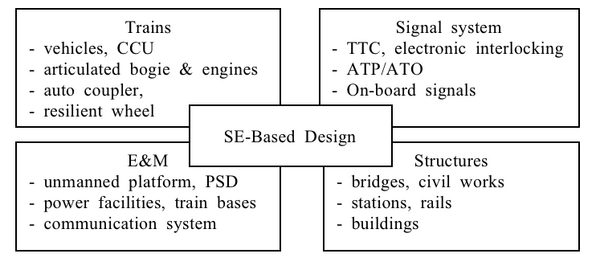
Figure 1. Subsystems of the SKLTS (Ahn, 2005). (Notes: CCU: Central Control Unit; TTC: Total Traffic Control; ATP: Automatic Train Protection; ATO: Automatic Train Operation; PSD: Platform Screen Door) Reprinted with permission of
Journal of the Korean Society for Railway. All other rights are reserved by the copyright owner.
The project life cycle for the SKLTS is summarized in Figure 2. It consisted of 7 phases: concept studies, concept development, preliminary design, design, system production and testing, performance evaluation, and operation/maintenance/close-out (OMC) - please see (Choi 2007) and (Chung et al. 2010) for further details. These phases, with the exception of the production and test phases, are completed through an evaluation and decision point (EDP) (milestonemilestone), depicted as a colored circle in Figure 2. These EDPs correspond to common life cycle artifacts such as requests for proposal (RFPs), proposals, preliminary design reviews (PDRs), and critical design reviews (CDRs).
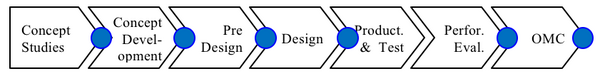
Figure 2. 7 phases of the SKLTS development (Ahn 2005). Reprinted with permission of the
Journal of the Korean Society for Railway. All other rights are reserved by the copyright owner.
During the SKLTS development, SE activities were focused on RAMS as summarized in Table 1.
Table 1. The SE Framework of the SKLTS (Ahn 2005). Reprinted with permission of the Journal of the Korean Society for Railway. All other rights are reserved by the copyright owner.
| Phases
|
Safety
|
Reliability
|
Function
|
Performance
|
| Concept studies
|
|
- Identifying RAM conditions
- RAM allocation
|
- System configuration
- Interface management
|
|
| Concept development & pre-design
|
- Safety planning
- Defining safety procedures & levels
|
- RAM planning
- Initial availability analysis
|
- Defining scenarios and alarm procedure
- Pre-designing command rooms
|
|
| Design
|
- Hazard log
- Safety case analysis
- Risk analysis
|
- Reporting RAM analysis
- RAM analysis of auxiliary systems
|
- Defining alarm systems
- Train analysis
- Functionality analysis of stations
|
|
| Performance evaluation
|
- Safety test planning & testing
|
- Verification and Validation (V&V) RAM
- Maintainability test
|
- System test planning and testing
|
- Performance test planning & testing
|
| Initial Operation
|
- System acceptance
- Driver certification
|
|
- Analyzing systems
- Identifying improvement points
|
|
*FRACAS: Failure Reporting & Corrective Action System
In the "concept studies" and "concept development" phases, requirements included the RAMS objectives. Planning activities in this phase included the scheduling of various tests and evaluations to be conducted after system design. The basic layout of rails and command rooms was also proposed. Finally, it was during this phase that interface management procedures and relationships between requirements and systems were defined. For RAMS engineering, it was also important to establish associated plans and criteria (e.g., RAM plans, safety plans, service availability, etc.).
During the pre-design phase, the basic architecture of the system was determined for safety planning, RAMS planning, and operational scenarios. Interfaces among subsystems, management procedures for contractors and legal regulations were defined. were defined as well as management procedures for contractors and legal regulations. The functional analysis dealt with timeline, accuracy of stop points, and trip times. Pre-design activities also included the specifications of major system elements such as signal systems, trains, and interfaces. For RAMS engineering, safety scenarios were defined, and the hazard and risk analyses were performed.
During the design and performance evaluation phases, hazard log and RAMS analyses were performed to ensure that each subsystem met safety requirements. The specifications of alarm systems and stations were also defined. In addition, V&V and test procedures were determined for performance evaluation. During the design phase, a design/construction interface manual (D/CIM) was developed and applied to ensure integrated and consistent design. (Bombardier, 2005.)
Because SKLTS was designed as an automatically-driven system, RAMS issues were critical to its success. The safety and reliability of the SKLTS were evaluated on a test railway that was constructed to standard specifications. Data was gathered from existing Korean light rail systems, as well as the light rail systems from other countries, to support V&V activities.
Various methods were applied for achieving the RAMS objectives, including RAMS requirements analysis, safety and RAMS planning, utilization of systems scenarios, and construction risk analysis.
Initial operation of SKLTS was allowed only after the system was formally accepted and operators were properly certified. During test operation, RAMS performance was continuously monitored and system scenarios were used successfully to evaluate the dynamic behavior of the system. A failure reporting and corrective action system (FRACAS) was used to gather accident and failure data. Continuous improvement when the system is in normal operation was identified as a requirement; the results from the FRACAS will be used to support improvement of the system, maintenance, and improvement of procedures.
Summary
Korean local authorities have successfully introduced the SKLTS to their precincts with some modifications. Successful examples include the Inchun Airport Line and the Seoul 9th Subway Line. One lesson learned that was identified was that requirement analysis, especially in the first few phases, should have been more complete.
References
Works Cited
Ahn, S.H. 2005. “Systems Engineering Applied to the Construction of Unmanned Light Rail Transit Systems.” Journal of the Korean Society for Railway. 8(2): 41-49.
Bombardier. 2005. Design/Construction Interface Manual. Montréal, Québec, Canada: Bombardier.
Choi, Y.C. 2007. "Systems eEngineering aApplication mModel for the nNational R&D pProject: Focusing on the rRailway sSystems." Ph.D. dissertation, Ajou University, Suwon, South Korea, 2007.
Chung, S. Y., S.G. Lee, D.W. Lee, and S.T. Jeon. 2010. “A sStudy on tThe aApplication mModel of sSystems eEngineering to Aadvance the bBusiness of the Light Rail Transit (LRT).” Proceedings on the Autumn Conference of the Korean Society for Railway, p. 24-30.
Primary References
None.
Additional References
Han, S.Y. and A.H. Lee. 2005. System Engineering for The Technology Development Program of Light Transit Systems: Internal Research Report. Gyeonggi-do, South Korea: Korea Railroad Research Institute.
Korean Agency for Technology and Standards. 2009. KSX ISO/IEC 15288: Life Cycle Processes of IT Systems Based on Systems and Software Engineering, Research Report. Gyeonggi-do, South Korea: Korean Agency for Technology and Standards.
Lee, W.D. 2002. “A study on the top-level functional analysis for the automated guideway transit by system engineering tools.” Proceedings of the Autumn Conference of the Korean Society for Railway, p. 202-207.
< Previous Article | Parent Article | Next Article >
SEBoK v. 2.9, released 20 November 2023

