Difference between revisions of "System Definition"
| Line 49: | Line 49: | ||
Other views of a system are possible to describe a more complete set of characteristics – refer to Architectural Frameworks (DoDAF, MODAF, NAF, etc.). | Other views of a system are possible to describe a more complete set of characteristics – refer to Architectural Frameworks (DoDAF, MODAF, NAF, etc.). | ||
| + | |||
| + | ==Top-down and recursive approach to system decomposition== | ||
| + | |||
| + | System Definition is managed through methodical top-down decomposition of the [[System of Interest (SoI) (glossary)]] into systems and System Elements. As the design process advances, emerging systems and System Elements form a ''System Breakdown Structure'' (SBS). For project management purpose, every system of the SBS may be included in a "building block", a notion introduced in (ANSI/EIA. 1998). | ||
| + | |||
| + | [[Stakeholder Requirement (glossary)|Stakeholder Requirements (glossary)]] and [[System Requirement (glossary)|System Requirements (glossary)]] exist at all layers of the SBS. In (ISO/IEC. 2011), these layers are known as levels of abstraction. As well as systematically introducing layers of design, the design process manages transformation of System Requirements through levels of abstraction. | ||
| + | |||
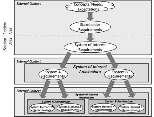
| + | Figure 1 portrays this approach. | ||
| + | |||
| + | *The white ovals represent requirements at decreasing levels of abstraction, and the arrows represent the transformation of those requirements through the levels. User, customer and other stakeholder expressions of needs, expectations, and constraints are transformed into Stakeholder Requirements, which represent the stakeholders’ view of the problem. | ||
| + | |||
| + | *The next transformation crosses the boundary between the problem and solution areas by converting Stakeholder Requirements into System Requirements, which represents the designer's view of the problem having potential solutions in mind. | ||
| + | |||
| + | *At the System-of-Interest level, the overall system architecture is developed that serves to identify systems and System Elements, and how they operate together the System of Interest Requirements. | ||
| + | |||
| + | Such design steps and requirements transformations are applied recursively as each system or System Element is identified. | ||
| + | |||
| + | [[File:SEBoKv05_KA-SystDef_Top-down_development_of_design_and_requirements.png|thumb|center|500px|center|Figure 1. Top-down Development of Design and Requirements (Figure Developed for BKCASE)]] | ||
| + | |||
| + | |||
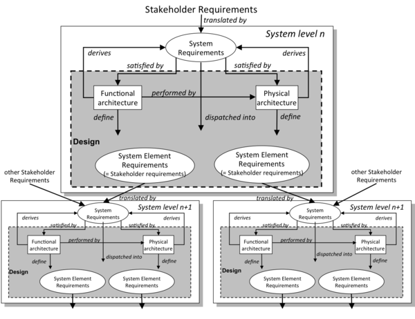
| + | This recursive approach to [[Requirements Engineering (glossary)]] recognizes that the same generic processes are applied at multiple levels of abstraction. Figure 2 below portrays the engineering that occurs in each system block. | ||
| + | As necessary System Elements are defined through sets of System Element Requirements, which come from assignment of design elements or from assignment of System Requirements. These lower-level requirements are in fact Stakeholder Requirements because they become inputs to other system blocks (level n+1). | ||
| + | |||
| + | [[File:SEBoKv075_KA-SystDef_Requirements_and_Design.png|thumb|center|400px|Figure 2. Requirements and Design in Each System Block (Figure Developed for BKCASE)]] | ||
| + | |||
| + | |||
| + | Figure 3 below shows how the generic block of Figure 2 above is recursively applied through the definition process. | ||
| + | |||
| + | At level n + 1, the systems or System Elements may also collect other Stakeholder Requirements that are directly pertinent to this level of design. Processes within each system are generic, but unique in local purpose, scope and context. | ||
| + | |||
| + | [[File:SEBoKv075_KA-SystDef_Recursive_instantiation.png|thumb|center|600px|center|Figure 3. Recursive Instantiation of Definition Process (Figure Developed for BKCASE)]] | ||
==Different understandings of “requirements”== | ==Different understandings of “requirements”== | ||
Revision as of 18:26, 7 March 2012
System definition is a set of core technical activities of systems engineering , including the activities that are completed primarily in the front-end portion of the system design . These consist of the definition of system requirements, design of the physical and logical system architecture, and system analysis.
System definition activities build on the artifacts and decisions from Concept Definition, primarily the articulation of the mission of the system of interest , the needs and requirements of stakeholders, and preliminary operational concepts. The products of system definition activities (system requirements, architecture, etc.) are inputs to System Realization. The specific activities and sequence of system definition activities will be dependent upon the type of life cycle model being utilized.
Topics
The topics contained within this knowledge area include:
- Fundamentals of System Definition
- System Requirements
- Architectural Design: Logical
- Architectural Design: Physical
- System Analysis
System Definition Activities
After the determination of the need for a new of modified system, System Definition activities activities are conducted to describe the system in detail using system requirements, architecture and design. The activities are grouped and described as generic processes that are performed iteratively and/or concurrently depending on the selected development cycle model . The processes involved with system definition include the development of system requirements, design of the physical and logical system architecture, and system analysis. The system definition processes and activities are also applied recursively at each successive level of the system hierarchy. (See the discussion of "iteration" and "recursion" in the Part 3 Introduction.
System Views and System Elements
To engineer a system, a set of engineering elements, characteristics, and properties have to be defined. These elements can be grouped in several views as follows.
Needs and Requirements view - Following characteristics provide a global understanding of the system in its context of use and seen as a black box.
- The purpose states the relevance of the system within the context of use. The purpose is the answer to questions “Why does the system exist? What is the relevance of its existence within the context? What is the usage of the system?”
- The mission expresses the set of services the system provides, the main and global transformation it performs. The mission is the answer to questions “What the system does? What service it provides?”
- The objectives are elements that quantify the mission, as a set of measurable data related to space, time and effectiveness. The objectives are the answers to questions: “How many inputs are transformed into outputs? What are the measures of effectiveness? How many times? etc. ”
- The expression of the mission is generally an abstraction of a set of actions performed by the system within its context of use and under operational conditions. This set of actions is called operational scenario and describes how these actions are related to each other and what they exchange with the elements of the context.
All these elements are refined iteratively until a comprehensive view of the system within its context is obtained. They are used to elicit needs, to define stakeholder requirements , and then system requirements .
Architectures view - Two complementary aspects of the system provide the fundamental basis of the system:
- The Logical Architecture supports the logical operation of the system all along its life cycle, and includes as a minimum Functional, Behavioral and Temporal views. Operational Scenarios refine the mission into a collection of Functions functions and dynamic structures that describe how mission is performed.
- The Physical Architecture is a set of system elements performing Functions of the system. Those System Elements can be either material or immaterial (e.g., equipments made of hardware, software and/or human roles).
These architectures are mapped onto each other. The interactions between System Elements are defined by interfaces whose complexity strongly depends on the way these architectures are designed.
Boundary and interface view - Boundary of the system depends on what engineers include within the scope of the system and outside of it. This view encompasses:
- input-output flows exchanged between the system and elements of its context of use (functional interface),
- physical interfaces (physical connections) that support these exchanges.
Interactions are modelled and defined using Operational Scenarios.
System breakdown view – Facing the potential number of System Elements that constitute the Physical Architecture, sets of System Elements can be grouped to form systems. So, the decomposition of the System of Interest (highest level) may include several layers of systems (intermediate levels of systems) until technological system elements (lowest level) are defined.
Because a System Element is primarily a system, it can be characterized in its turn using the previous views in its own context. But the context of a system can also be viewed as a system. The notion of system as described and defined here is recursive.
Other views of a system are possible to describe a more complete set of characteristics – refer to Architectural Frameworks (DoDAF, MODAF, NAF, etc.).
Top-down and recursive approach to system decomposition
System Definition is managed through methodical top-down decomposition of the system of interest (soi) into systems and System Elements. As the design process advances, emerging systems and System Elements form a System Breakdown Structure (SBS). For project management purpose, every system of the SBS may be included in a "building block", a notion introduced in (ANSI/EIA. 1998).
stakeholder requirements and system requirements exist at all layers of the SBS. In (ISO/IEC. 2011), these layers are known as levels of abstraction. As well as systematically introducing layers of design, the design process manages transformation of System Requirements through levels of abstraction.
Figure 1 portrays this approach.
- The white ovals represent requirements at decreasing levels of abstraction, and the arrows represent the transformation of those requirements through the levels. User, customer and other stakeholder expressions of needs, expectations, and constraints are transformed into Stakeholder Requirements, which represent the stakeholders’ view of the problem.
- The next transformation crosses the boundary between the problem and solution areas by converting Stakeholder Requirements into System Requirements, which represents the designer's view of the problem having potential solutions in mind.
- At the System-of-Interest level, the overall system architecture is developed that serves to identify systems and System Elements, and how they operate together the System of Interest Requirements.
Such design steps and requirements transformations are applied recursively as each system or System Element is identified.
This recursive approach to Requirements Engineering (glossary) recognizes that the same generic processes are applied at multiple levels of abstraction. Figure 2 below portrays the engineering that occurs in each system block.
As necessary System Elements are defined through sets of System Element Requirements, which come from assignment of design elements or from assignment of System Requirements. These lower-level requirements are in fact Stakeholder Requirements because they become inputs to other system blocks (level n+1).
Figure 3 below shows how the generic block of Figure 2 above is recursively applied through the definition process.
At level n + 1, the systems or System Elements may also collect other Stakeholder Requirements that are directly pertinent to this level of design. Processes within each system are generic, but unique in local purpose, scope and context.
Different understandings of “requirements”
To avoid confusion in the multitude of terms around requirement consider the following classifications:
- Process role or state: It is the role the requirement plays in the Definition process; for instance, its position in the system block: translated, derived, satisfied; or its state of agreement: Proposed, Approved, Cancelled.
- Level of abstraction: It is the level within the Definition process for the requirement stands; for instance, Stakeholder Requirement, System Requirement, System Element Requirement.
- Type of requirement: It is the nature of the requirement itself; for instance Functional, Performance, Constraint.
Any single requirement may simultaneously be in a particular state, at a particular level abstraction, and of a particular type.
None of the main standards attempt to normalize this kind of requirement state and role. However, ANSI/EIA 632 (ANSI/EIA. 1998) makes reference to requirements roles by referring to “Specified Requirements” (corresponding to an output requirement resulting from the design process of a particular system) and to “Assigned Requirements” (corresponding to input requirements to a system that have flowed down from a higher level.) In the formulation of Figure 2 and Figure 3, “Specified Requirements” and “Assigned Requirements” are in fact the same requirements viewed from different contexts. Type of requirements may also evolve through levels of abstraction. For example, a safety requirement in a lift system becomes implemented as a braking function on the cabin cables. For additional explanations about differences between stakeholder, user, and customer, and between kinds of requirements, refer to (Martin, J. N. 1997) chapter 2.
System Architecture
Within the Systems Engineering community, notions of architecture seem to have been heavily influenced by ISO/IEC 15288, which even today presents a somewhat implicit view of architecture, conflating it with design as part of a single process step called “Architectural Design”.
The lack of a full treatment of architecture by the Systems Engineering community has encouraged a variety of other disciplines to emerge to fill the gap left by systems engineers. These include the Systems architecting discipline (Maier, M., and E. Rechtin. 2009), which purportedly sits above systems engineering, and Enterprise Architecting, which in one viewpoint is concerned with structuring the Enterprise, and in another viewpoint is concerned with the IT systems supporting the Enterprise.
Although there are diverse viewpoints on architecture, the different perspectives have much in common. We consider systems engineering to cover all aspects of the creation of a system, including system architecture.
Definitions
See the entry architecture .
Some Common Concepts
The majority of interpretations of system architecture are based on the fairly intangible notion of structure – i.e. relationships between elements.
Some authors limit the types of structure considered to be architectural, say for example restricting themselves to functional and physical structure. Recent practice has extended consideration to include temporal and other dimensions of structure within specified architectural frameworks (e.g DODAF, MODAF) – refer to (DODAF, 2010) and (MODAF, 2010).
Sometimes, the notion of architecture is expanded to include meta-structure, for example relating to structuring principles across a family of systems rather than specific structures or principles for the evolution of an architecture over time (e.g. IEEE 1471).
While architectural concepts are very useful and widely used in Systems Engineering, there is a lack of consistency across communities of practice with potential for confusion. An attempt to develop and apply a systematic approach to characterizing architecture "Belief Systems" in Systems Engineering has been described by the INCOSE UK Architecture Working Group – refer to (Wilkinson et al. 2010) and (Wilkinson 2010).
A discussion of the features of systems architectures can be found in (Maier, M., and E. Rechtin. 2009).
System design
Principles, rules, heuristics
Designing the architecture of a system consists of imagining in a structured way solutions that are supported by universal principles and rules.
Experienced designers use a lot of heuristics that are basic constructions learned from experience. When an issue is identified through System Requirements, heuristics may (or may not) be able to address the issue. Principles, rules, heuristics that govern systems can be classified as:
- Static domain relates to physical design, in other words, physical structure or organization of the System of Interest, which is broken into systems and system elements . It deals with partitioning systems and System Elements (i.e., grouping System Elements into systems and/or separation of systems in System Elements) and Physical Interfaces between System Elements.
- Dynamic domain relates to logical design, in particular to the behavior of the system. It includes a description of Functions (i.e. transformations of Input/Output Flows) and interactions between functions of the system and between those of the external objects or systems. It takes into account reactions to events that launch or stop the execution of functions of the system. It deals also with effectiveness (performances, operational conditions) of the system.
- Temporal domain concerns temporal invariance levels of the execution of functions of the system. This means that every function is executed according to cyclic or synchronous characteristics. It includes also decisional levels that are asynchronous characteristics of the behavior of some functions.
- Environmental domain relates to enablers (Production, Logistics Support, etc.), but also to survivability of the system in reaction to natural hazards or threats, and to integrity of the system in reaction to internal potential hazards. This includes, for example, climatic, mechanical, electromagnetic, and biological aspects.
More detailed classification can be found in (Maier, M., and E. Rechtin. 2009).
Transition from System Requirements to Physical Architecture
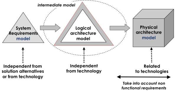
The aim of the approach is to progress from System Requirements (representing the problem from a supplier/designer point of view, as much as possible independent of technology) to an intermediate model of logical architecture , then to allocate the elements of the Logical Architecture to elements of potential Physical Architectures. Design decisions and technological solutions are selected according to performance criteria and non-functional requirements such as operational conditions and life cycle constraints (e.g., environmental conditions, maintenance constraints, realization constraints, etc.) – see Figure 4.
Iterations between Logical and Physical Architecture Design
Design activities require spending several iterations from logical design to physical design and vice versa until both logical and physical architectures are exhaustive and consistent. The first design activity is the creation of a logical architecture based on nominal scenarios (of functions). Physical design then enables to determine main System Elements that could perform system Functions and to organize them into a Physical Architecture.
A second logical design loop allows taking into account allocations of Functions to System Elements and derived functions coming from physical solution choices, as well as supplementing the initial logical model by introducing other scenarios, failure analyses, and every operational requirement not taken before. Derived Functions must, in their turn, be allocated to System Elements, and this, in turn, affects physical design.
Other design loops must be considered to produce an exhaustive and consistent logical and physical solution. During design, technological choices lead potentially to new Functions, new Input/Output and Control Flows, and new Physical Interfaces. These new elements can conduct to creation of new System Requirements, called “derived requirements”.
Concept of interface
The concept of interface is one of the most important to consider when designing the architecture of a system. The term “interface” comes from Latin words "inter" and "face" and means “to do something between things”. Therefore, the fundamental aspect of an interface is functional and is defined as inputs and outputs of functions. As Functions are performed by physical elements, inputs/outputs of functions are also carried by physical elements, called Physical Interfaces. Consequentially, both functional and physical aspects are considered in the notion of interface. A detailed analysis of an interface shows the Function “send,” located in one System Element, the Function “receive,” located in the other one, and the Function “carry,” performed by the Physical Interface which supports the Input/Input Flow – see Figure 5.
In the context of complex exchanges between System Elements (IT systems), a protocol is seen as a Physical Interface that carries exchanges of data.
Re-use of System Elements
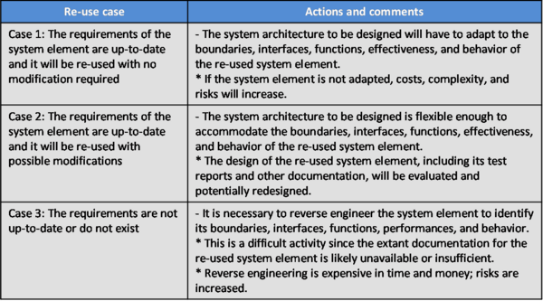
Systems frequently incorporate existing System Elements. This re-use constraint has to be identified as a System Requirement and carefully taken into account during design. One can distinguish three general cases when re-using System Elements. Table 1.
Re-use may introduce risks that can be significant for the project (costs, deadlines, complexity). Disappointment can be severe because of the widespread false idea that re-use is free.
References
Works Cited
Faisandier, A. 2011 (unpublished). Engineering and Architecting Multidisciplinary Systems.
Primary References
ANSI/EIA. 1998. Processes for Engineering a System. Philadelphia, PA, USA: American National Standards Institute (ANSI)/Electronic Industries Association (EIA), ANSI/EIA 632-1998.
INCOSE. 2010. Systems Engineering Handbook: A Guide for System Life Cycle Processes and Activities. Version 3.2.1. San Diego, CA, USA: International Council on Systems Engineering (INCOSE), INCOSE-TP-2003-002-03.2.1
ISO/IEC. 2003. Systems Engineering – A Guide for The Application of ISO/IEC 15288 System Life Cycle Processes. Geneva, Switzerland: International Organization for Standardization (ISO)/International Electronical Commission (IEC), ISO/IEC 19760:2003 (E).
ISO/IEC. 2007. Systems Engineering – Application and Management of The Systems Engineering Process. Geneva, Switzerland: International Organization for Standards (ISO)/International Electronical Commission (IEC), ISO/IEC 26702:2007.
ISO/IEC 2008. Systems and Software Engineering -- System Life Cycle Processes. Geneva, Switzerland: International Organisation for Standardisation / International Electrotechnical Commissions / Institute for Electrical and Electronics Engineers. ISO/IEC/IEEE 15288:2008.
NASA. 2007. Systems Engineering Handbook. Washington, D.C., USA: National Aeronautics and Space Administration (NASA). NASA/SP-2007-6105.
Additional References
Faisandier. 2011 (unpublished). Engineering and Architecting Multidisciplinary Systems.
Hitchins, D. 2007. Systems Engineering: A 21st Century Systems Methodology. Hoboken, NJ, USA: John Wiley & Sons.
ISO. 2007. Systems Engineering and Design. Geneva, Switzerland: International Organization for Standardization (ISO). ISO 10303-AP233.
Jackson, S., D. Hitchins, and H. Eisner. 2010. "What is the Systems Approach?" INCOSE Insight (April 2010): 41-43.
Oliver, D., T. Kelliher, and J. Keegan. 1997. Engineering Complex Systems with Models and Objects. New York, NY, USA: McGraw-Hill.


