System Definition
Introductory Paragraphs
Topics
The topics contained within this knowledge area include:
- Fundamentals of System Definition
- Mission Analysis and Stakeholders Requirements
- System Requirements
- Architectural Design
- System Analysis
Introduction to System Definition Knowledge Area
System Definition activities
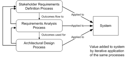
The SEBOK divides the traditional life cycle process steps into four stages. This chapter will discuss the definition stage. System Definition is the set of technical creative activities of systems engineering (SE). The activities are grouped and described as generic processes that are performed iteratively and concurrently depending of the selected development cycle or life cycle . The activities of a process are not performed only on a sequential mode but they may interact with activities of other related processes. The processes of System Definition include mission analysis and stakeholder requirements, system requirements, architectural design, and system analysis. The Figure below gives an example of iteration of three processes as defined in ISO-IEC 15288.
Figure 1. Example of iterations of processes related to System Definition (ISO. 2003)
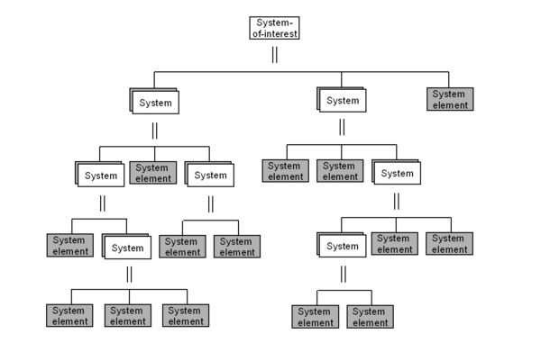
The complete definition of a system of interest (soi) is generally achieved considering decomposition layers of systems and of system elements . The Figure below presents a fundamental schema of a system breakdown structure.
Figure 2. Hierarchical decomposition of a system-of-interest (ISO/IEC. 2008)
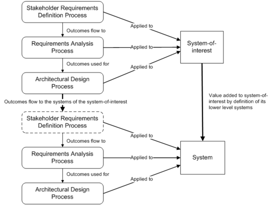
In each decomposition layer and for each system, the System Definition processes are applied recursively because the notion of system is recursive; a System of Interest, a system, a system elements have the same nature – see Part 2. The Figure below shows an example of recursion of three processes as defined in ISO-IEC 15288.
Figure 3. Recursion of processes on layers (ISO. 2003)
Note: To facilitate readers' understanding of the standard ISO/IEC. 2008, the Figure below shows the relative position of the Technical Knowledge Areas (KA) of this SEBoK with respect to the processes as stated in the standard.
Figure 4. Mapping of technical topics of Knowledge Areas of SEBoK with ISO/IEC 15288 Technical Processes
Top-down approach: from the problem to the solution
In a top-down approach, the System Definition activities are focused primarily on understanding the problem, the conditions that constrain the system, and the design of solutions. The outcomes of the System Definition are used for the System Realization, System Deployment and Use, and Product and Service Life Management. In this approach, System Definition includes the activities that are completed primarily in the front-end portion of the system design and the design itself. These consist of mission analysis and stakeholders’ requirements, system requirements, architectural design, and system analysis.
- Mission Analysis and stakeholder requirements focus on the identification and definitions of stakeholders' needs, the development of operational and environmental conditions, of operational concepts, and the definition of applicable constraints.
- These elements then are used for the development of System Requirements (glossary) that consists of the refinement and translation of the stakeholders’ requirements into System (technical) Requirements.
- These System Requirements are then utilized as inputs to the Architectural Design, which includes functional architecture , dynamic behavior, and Physical Architecture (glossary)in addition to temporal and decision levels.
- System Analysis studies are performed to evaluate and select potential System Elements that compose the system and to compare potential architectures and to select the most suitable one. Finally, System Analysis provides a “best value” balanced solution involving all the relevant engineering elements (Stakeholder Requirements, System Requirements, and architectural Design Properties).
Bottom up approach and evolution of the solution
During the product and service Life Management, and because of evolution of the context of use, or for improvement purpose of the existing solution, engineers are led to reconsider the System Definition in order to modify or adapt some structural, functional, or temporal properties. Before attempting to any modification, and because of the existence of the System of Interest, a reverse engineering is often necessary to (re)characterize its own properties or those of its systems or system elements.
A bottom-up approach is necessary for analysis purposes, or for (re)using existing elements into design architecture . On the contrary, a top-down approach in generally used to define a design solution corresponding to a problem or a set of needs.
So, in the real life of a System of Interest, bottom-up and top-down approaches are often mixed in order to engineer new solutions and/or to re-engineer or re-use existing Products, Services, Enterprises, physical or functional models, requirements, etc.
Separation and iteration between Problem Area and Solution Area
Inside the System Definition activities, the Systems Engineering discipline makes a significant distinction between the definition of the problem and the design of the solution. Too often, the design team will develop solutions elements ("how the system must be done") without sufficiently defining the problem to be solved and the constraints to respect ("what the system must do").
To correctly engineer a system, it is recommended to use in a first step a top-down approach differentiating the activities that treat the problem area in terms of needs, expectations, constraints, and requirements from those that treat the solution area in terms of functional, behavioral, physical design. Nevertheless, the two must work together and iteratively. The design of the solution is made of decisions and trade-offs according to requirements, constraints and enterprises capabilities (know-how, technological control, financial capability, etc.). This work requires several iterations tuning the couple "problem-solution". System Analysis activities are used to perform the link between the two areas.
The distinction between the two areas shall be effective on each level of the system breakdown structure – see Figure 2 above.
Most of the time, the systems are not created from scratch and generally integrate existing system elements . A bottom-up approach is used in parallel of the top-down approach to take into account such elements (as legacy systems or products and services for example), and consists to identify the services and capabilities they provide in order to define applicable interface requirements and constraints.
Ontology for System Development
Why an ontology for system development?
Ontology is the set of entities presupposed by a theory (Collins English Dictionary). SE, and in particular system development, can be considered a theory because it is based on mathematical concepts, even if it is not always described as such. A SE ontology can be defined considering the following path.
SE provides engineers with an approach based on a set of concepts (i.e. Stakeholder, Requirement, Function, Scenario, System Element, etc.) and generic processes. Each process is composed of a set of activities and tasks federated around a theme or a purpose. A process describes “what to do” using the concepts. The implementation of the activities and tasks is supported by methods and modeling techniques, composed themselves of elementary tasks; they describe the “how to do”. The activities and tasks of SE are transformations of generic data using the predefined concepts. Those generic data are called Entities, Classes, or Types. Each entity is characterized by specific attributes, and each attribute can get different values. All along their execution, the activities and tasks of processes, methods, and modeling techniques exchange instances of generic entities according to logical relationships. These relationships allow the engineer to link the entities between themselves (traceability) and to follow a logical sequence of the activities and the global progression (engineering management). Cardinality is associated with every relationship, expressing the minimum and maximum number of entities in order to make the relationship valid. Additional information may be found in (Oliver, Kelliher, and Keegan. 1997).
The set of SE entities and their relationships form an ontology also often called Engineering Meta-model. Such an approach is used and defined in the standard (ISO 2007). The benefits of using an ontology are many. The ontology allows or forces:
- the use of a standardized vocabulary, using the right names and avoiding using synonyms in the processes, methods, and modeling techniques;
- reconcilement of the vocabulary used in different modeling techniques and methods;
- the automatic appearance of traceability of requirements when implemented in databases, SE tools or workbenches, and also the quick identification of the impacts of modifications in the engineering data set;
- checks of the consistency and completeness of engineering data, etc.
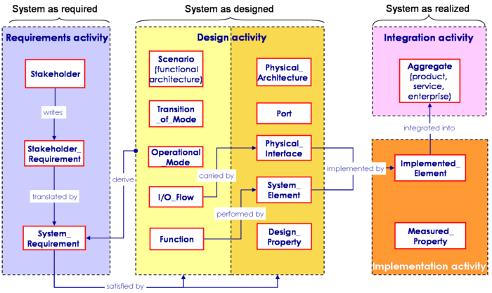
An engineering ontology can be represented using Entity-Relationship Diagrams or Classes Diagrams. The Figure below shows a simplified and truncated view of a meta-data model for system development. The entities are logically grouped according to the activities of development. One can distinguish three views of the system that correspond also to three status of the system:
- the system "as required", represented by system requirements that are obtained by refinement of the stakeholder requirements ;
- the system "as designed", represented by functional architecture and behavioral models or scenarios (generally composed of functions , input-output flows , and/or operational modes and transition of modes and by physical architecture models (composed of systems elements , physical interfaces , Port (glossary) and their associated Design Properties;
- the system "as realized", represented by a product , a service or an enterprise that integrates Implemented Elements (glossary) characterized by a set of Measured Properties (glossary).
Figure 5. A simplified view of a meta-data model for system development (Faisandier. 2011)
As they are progressively instantiated, the entities and their relationships represent also the maturity of the progress of the development of the system. Rather than providing a fixed work flow of activities, the relationships between the entities allow to select several threats of activities and tasks depending of the project type, and of the availability of the engineering data at a given time.
Approaches supported by the ontology
Such ontology supports easily different approaches for life cycle purposes such as top-down, bottom-up or mixed approaches.
- A top-down approach can be used starting from the left of the diagram such as:
- Stakeholders write Stakeholder Requirements that are then translated by System Requirements;
- those last are then satisfied by design elements, in particular Functions that are then performed by System Elements, and Input-Output Flows that are carried by Physical Interfaces;
- the System Elements and Physical Interfaces are implemented by Implemented Elements depending of the selected technologies;
- finally these last elements are integrated into intermediate aggregates till obtaining the final realized System of Interest (Product, Service or Enterprise).
All along the design activity, the Design Properties of the system architecture can be assessed and compared to assessment criteria extracted from the System Requirements. This allows to identify discrepancies, and then to tune the design or to decide modifications of the requirements (System Analysis). When the system is realized and in operation, the Measured Properties can be compared to the Design Properties and to the System Requirements. These comparisons allow to identify the correct performance of the system, and to decide eventually maintenance operations.
- But a bottom-up approach associated to reverse engineering can also be used in order to re-structure / architect existing systems to fit with the evolution of the context of use.
- First the Implemented Elements are identified, and then the System Elements and Physical Interfaces that correspond are identified in their turn.
- The second step of reverse engineering consists to identify the Functions performed by the System Elements and the Input-Output Flows carried by the Physical Interfaces. This makes possible to establish physical and functional architecture models of the existing system.
- Finally, it is possible to characterize the existing system by a set of Design Properties and System Requirements extracted from Physical and Functional Architecture models.
- Any modification of what exists (re-engineering) is then possible reconsidering new System Requirements or evolutions in a top-down approach.
Because of evolution of the context of use of a system during its life cycle, it is essential that the set of its engineering data and models are permanently consistent, updated and accessible.
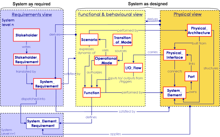
The Figure below shows a synthetic view of the same meta-data model as above but restricted to System Definition and extended with the main relationships used during System Definition.
Figure 6. A simplified ontology for System Definition (Faisandier. 2011)
Based on the overview of the figure above, a set of major entities, attributes, and relationships are suggested and detailed in the topics of the System Definition knowledge area.
References
Please make sure all references are listed alphabetically and are formatted according to the Chicago Manual of Style (15th ed). See the BKCASE Reference Guidance for additional information.
Citations
List all references cited in the article. Note: SEBoK 0.5 uses Chicago Manual of Style (15th ed). See the BKCASE Reference Guidance for additional information.
ISO/IEC. 2003. Systems Engineering — A Guide for the application of ISO/IEC 15288 System Life Cycle Processes. Geneva, Switzerland: International Organization for Standardization (ISO)/International Electronical Commission (IEC), ISO/IEC 19760:2003 (E).
ISO/IEC. 2008. Systems and software engineering - system life cycle processes. Geneva, Switzerland: International Organization for Standardization (ISO)/International Electronical Commission (IEC), ISO/IEC 15288:2008 (E).
Oliver, D., T. Kelliher, and J. Keegan. 1997. Engineering complex systems with models and objects. New York, NY: McGraw-Hill.
ISO. 2007. Systems engineering and design. Geneva, Switzerland: International Organization for Standardization (ISO), ISO 10303-AP233.
Faisandier. 2011. Engineering and architecting multidisciplinary systems. (expected--not yet published).
Primary References
All primary references should be listed in alphabetical order. Remember to identify primary references by creating an internal link using the ‘’’reference title only’’’ (title). Please do not include version numbers in the links.
ANSI/EIA. 1998. Processes for engineering a system. Philadelphia, PA, USA: American National Standards Institute (ANSI)/Electronic Industries Association (EIA), ANSI/EIA-632-1998.
INCOSE. 2010. INCOSE systems engineering handbook, version 3.2. San Diego, CA, USA: International Council on Systems Engineering (INCOSE), INCOSE-TP-2003-002-03.2.
ISO/IEC. 2003. Systems Engineering — A Guide for the application of ISO/IEC 15288 System Life Cycle Processes. Geneva, Switzerland: International Organization for Standardization (ISO)/International Electronical Commission (IEC), ISO/IEC 19760:2003 (E).
ISO/IEC. 2007. Systems engineering--application and management of the systems engineering process. Geneva, Switzerland: International Organization for Standards (ISO)/International Electronical Commission (IEC), ISO/IEC 26702:2007.
ISO/IEC. 2008. Systems and software engineering - system life cycle processes. Geneva, Switzerland: International Organization for Standardization (ISO)/International Electronical Commission (IEC), ISO/IEC 15288:2008 (E).
NASA. 2007. Systems engineering handbook. Washington, D.C.: National Aeronautics and Space Administration (NASA), NASA/SP-2007-6105.
Additional References
All additional references should be listed in alphabetical order.
Faisandier. 2011. Engineering and architecting multidisciplinary systems. (expected--not yet published).
ISO. 2007. Systems engineering and design. Geneva, Switzerland: International Organization for Standardization (ISO), ISO 10303-AP233.
Oliver, D., T. Kelliher, and J. Keegan. 1997. Engineering complex systems with models and objects. New York, NY: McGraw-Hill.
