Difference between revisions of "System Implementation"
(No difference)
|
Revision as of 21:04, 9 August 2011
Introductory Paragraph(s)
Introduction, Definition and Purpose
Introduction - Implementation uses the structure created during Architectural Design and the results of System Analysis to construct System Elements that meet the Stakeholder Requirements and System Requirements developed in the early life cycle phases. These System Elements are then integrated to form intermediate aggregates and finally the complete system-of-interest. See System Integration.
Definition and Purpose - Implementation is the process that actually yields the lowest-level System Elements in the system hierarchy (system breakdown structure). The System Elements are made, bought, or reused. Production involves the hardware fabrication processes of forming, removing, joining, and finishing; or the software realization processes of coding and testing; or the operational procedures development processes for operators' roles. If implementation involves a production process, a manufacturing system which uses the established technical and management processes may be required.
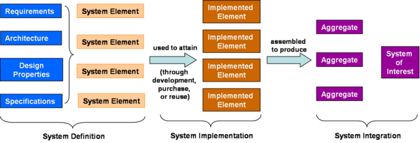
The purpose of the implementation process is to design and create or fabricate a System Element conforming to that element’s design properties and/or requirements. The element is constructed employing appropriate technologies and industry practices. This process bridges the System Definition Processes and the Integration process. Figure 1 below portrays how the outputs of System Definition relate to System Implementation, which produces the Implemented (System) Elements required to produce Aggregates and the System of Interest.
Figure 1 - Simplification of how the outputs of System Definition relate to System Implementation. (Developed for BKCASE)
Process Approach
Purpose and Principle of the approach
During the implementation process, engineers apply the design properties and/or requirements allocated to a system element to design and produce a detailed description. They then fabricate, code, or build each individual element using specified materials, processes, physical or logical arrangements, standards, technologies, and/or information flows outlined in detailed description (drawings or other design documentation). This System Element will be verified against the detailed description of properties and validated against its requirements.
If subsequent verification and validation actions or configuration audits reveal discrepancies, recursive interactions occur with predecessor activities or processes as required to mitigate those discrepancies and to modify, repair, or correct the System Element in question.
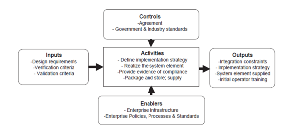
Figure 2 provides the context for the implementation process from the perspective of DAU.
TO BE CHANGED, SAME AS FIG 3
Figure 2 - Context Diagram for the Implementation Process / DAU (Source: (DAU February 19, 2010)/Released)
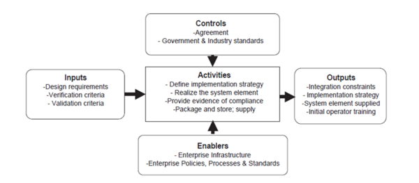
The International Council on Systems Engineering (INCOSE) provides a similar, but somewhat more detailed view on the context of implementation, as seen in Figure 3.
Figure 3 - Context diagram for the implementation process / INCOSE (INCOSE. 2010)
These figures provide a useful overview of the systems engineering community’s perspectives of what is required for implementation and what the general results of implementation may be. These are further supported by the discussion of implementation inputs, outputs, and activities found in the National Aeronautics and Space Association (NASA) Handbook. (NASA. 2007). It is important to understand that these views are process-oriented. While this is a useful model, examining implementation only in terms of process can be limiting.
Depending on the technologies and systems chosen when a decision is made to produce a System Element, the implementation process outcomes may generate constraints to be applied on the architecture of the higher-level system; those constraints are normally identified as derived System Requirements and added to the set of System Requirements applicable to this higher-level system. The architectural design has to take those constraints into account.
If the decision is made to purchase or reuse an existing System Element, this has to be identified as a constraint or System Requirement applicable to the architecture of the higher-level system. Conversely, the implementation process may involve some adaptation or adjustments to the System Requirement in order to be integrated into a higher-level system or aggregate.
Implementation also involves packaging, handling, and storage, depending on the concerned technologies and where or when the System Requirement needs to be integrated into a higher-level aggregate. Developing the supporting documentation for the System Requirement, such as the manuals for operation, maintenance, and/or installation, is also a part of the implementation process.
The System Element Requirements and the associated verification and validation criteria are inputs to this process; these inputs come from the Architectural Design process detailed outputs.
Execution of the implementation process is governed by standards, both industry and government, and the terms of all applicable agreements. This may include conditions for packaging and storage as well as preparation for use activities, such as operator training. In addition, packaging, handling, storage, and transportation (PHS&T) considerations will constrain the implementation activities. For more information, refer to the discussion of PHS&T in the System Deployment and Use. In addition, the developing or integrating organization will likely have enterprise-level safety practices and guidelines that must also be considered.
Activities of the Process
Major activities and tasks performed during this process include:
- Define the implementation strategy. Implementation process activities begin with detailed design and include developing an Implementation Strategy that defines fabrication and coding procedures, tools and equipment to be used, implementation tolerances, and the means and criteria for auditing configuration of resulting elements to the detailed design documentation. In the case of repeated system element implementations (such as for mass manufacturing or replacement elements), the implementation strategy is defined and refined to achieve consistent and repeatable element production; it is retained in the project decision database for future use. The implementation strategy contains the arrangements for packing, store and supply the Implemented Element.
- Realize the System Element. Realize or adapt and produce the concerned System Element using the implementation strategy items as defined above. Realization or adaptation is conducted with regard to standards that govern applicable safety, security, privacy, and environmental guidelines or legislation and the practices of the relevant implementation technology. This requires the fabrication of hardware elements, development of software elements, definition of training capabilities and drafting of training documentation, and the training of initial operators and maintainers.
- Provide evidence of compliance. Record evidence that the System Element meets its requirements and the associated verification and validation criteria as well as the legislation policy. This requires the conduction of peer reviews and unit testing as well as inspection of operation and maintenance manuals. Acquire Measured Properties that characterize the Implemented Element (weight, capacities, effectiveness, level of performance, reliability, availability, etc.)
- Package, store and supply the Implemented Element. This should be defined in the implementation strategy.
Artifacts and Ontology Elements
This process may create several artifacts such as:
- Implemented System
- Implementation Tools
- Implementation Procedures
- Implementation Plan or Strategy
- Verification Reports
- Issue / Anomaly / Trouble Report
- Change Request (about design)
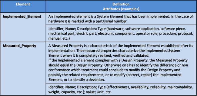
This process handles the ontology elements of Table 1.
Table 1 - Main ontology elements as handled within System Element implementation
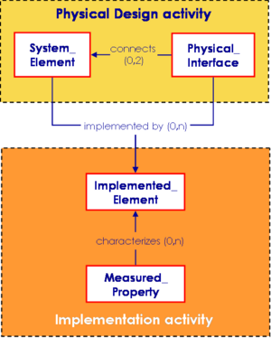
The main relationships between ontology elements are presented in Figure 4.
Figure 4 - Implementation elements relationships with other engineering elements. (Faisandier, 2011)
Methods, Techniques and Tools
There are many software tools available in the implementation and integration phases. The most basic method would be the use of N-Square diagrams as discussed in Jeff Grady’s book on System Integration. (Grady. 1994)
Checking and Correctness of Implementation
Proper implementation checking and correctness should include testing to determine if the Implemented Element, i.e. piece of software, hardware, or other product, works in its intended use. Testing could include mockups and breadboards as well as modeling and simulation of a prototype or completed pieces of a system. Once this is completed successfully, then the next process would be system integration.
References
Please make sure all references are listed alphabetically and are formatted according to the Chicago Manual of Style (15th ed). See the BKCASE Reference Guidance for additional information.
Citations
List all references cited in the article. Note: SEBoK 0.5 uses Chicago Manual of Style (15th ed). See the BKCASE Reference Guidance for additional information.
DAU. February 19, 2010. Defense acquisition guidebook (DAG). Ft. Belvoir, VA, USA: Defense Acquisition University (DAU)/U.S. Department of Defense.
INCOSE. 2010. INCOSE systems engineering handbook, version 3.2. San Diego, CA, USA: International Council on Systems Engineering (INCOSE), INCOSE-TP-2003-002-03.2.
NASA. December 2007. Systems engineering handbook. Washington, D.C.: National Aeronautics and Space Administration (NASA), NASA/SP-2007-6105.
Grady, J. O. 1994. System integration. Boca Raton, FL, USA: CRC Press, Inc.
Primary References
All primary references should be listed in alphabetical order. Remember to identify primary references by creating an internal link using the ‘’’reference title only’’’ (title). Please do not include version numbers in the links.
DAU. February 19, 2010. Defense acquisition guidebook (DAG). Ft. Belvoir, VA, USA: Defense Acquisition University (DAU)/U.S. Department of Defense.
INCOSE. 2010. INCOSE systems engineering handbook, version 3.2. San Diego, CA, USA: International Council on Systems Engineering (INCOSE), INCOSE-TP-2003-002-03.2.
NASA. December 2007. Systems engineering handbook. Washington, D.C.: National Aeronautics and Space Administration (NASA), NASA/SP-2007-6105.
Grady, J. O. 1994. System integration. Boca Raton, FL, USA: CRC Press, Inc.
Additional References
All additional references should be listed in alphabetical order.
