|
|
| (271 intermediate revisions by 15 users not shown) |
| Line 1: |
Line 1: |
| − | There are a large number of life cycle process models in which systems engineering may operate. For the most part, these models fall into three major categories: | + | ---- |
| − | | + | '''''Lead Authors:''''' ''Dick Fairley, Kevin Forsberg'', '''''Contributing Author:''''' ''Ray Madachy, Phyllis Marbach'' |
| − | #Primarily Prespecified and Sequential Processes.
| + | ---- |
| − | #Primarily Evolutionary and Concurrent Processes. Examples are the Rational Unified Process and various forms of the Vee and spiral models.
| + | There are a large number of [[Life Cycle Models|life cycle process models]]. As discussed in the [[System Life Cycle Process Drivers and Choices]] article, those models described fall into three major categories: (1) primarily pre-specified single-step or multistep, also known as traditional or sequential processes; (2) evolutionary sequential (or the Vee Model) and (3) evolutionary opportunistic and evolutionary concurrent (or incremental agile). The concurrent processes are known by many names: the agile unified process (formerly the Rational Unified Process), the spiral models) and include some that are primarily interpersonal and unconstrained processes (e.g., agile development, Scrum, extreme programming (XP), the dynamic system development method, and innovation-based processes). |
| − | #Primarily Interpersonal and Unconstrained Processes. Examples are Agile development, Scrum, eXtreme Programming, Dynamic System Development Method, and innovation-based processes.
| |
| − | | |
| − | The Vee Model represents the primarily prespecified and sequential models. The Incremental Commitment Spiral Model (ICSM) represents the primarily evolutionary and concurrent models. The Scrum Model represents the primarily interpersonal and unconstrained processes.
| |
| | | | |
| − | There are considerable gray areas among the categories. Versions of the Vee model show concurrent system development, verification, and validation activities, although the language and tables describing the Vee model below generally assign activities to stages more exclusively and sequentially. The ICSM has a prespecified approach for developing increments, while destabilizing change traffic is routed to a concurrent agile rebaselining team as in Figure 2. Organizations have found ways to scale up agile methods to projects of up to 100 people using a Scrum of Scrums approach within and overall architecture. Furthermore, very large systems and systems of systems will generally find it best to apply all three process categories to portions of their systems and their life cycles.
| + | This article specifically focuses on the Vee Model as the primary example of pre-specified and sequential processes. In this discussion, it is important to note that the Vee model, and variations of the Vee model, all address the same basic set of systems engineering (SE) activities. The key difference between these models is the way in which they group and represent the aforementioned SE activities. |
| | | | |
| | + | General implications of using the Vee model for system design and development are discussed below; for a more specific understanding of how this life cycle model impacts systems engineering activities, please see the other knowledge areas (KAs) in Part 3. |
| | | | |
| − | ==A Primarily Prespecified and Sequential Process Model: The Vee Model== | + | ==A Primarily Pre-specified and Sequential Process Model: The Vee Model == |
| − | | + | The sequential version of the Vee Model is shown in Figure 1. Its core involves a sequential progression of plans, specifications, and products that are baselined and put under configuration management. The vertical, two-headed arrow enables projects to perform concurrent opportunity and risk analyses, as well as continuous in-process validation. The Vee Model encompasses the first two life cycle stages listed in the "Generic Life Cycle Stages their purposes, and decision gate options" table of the INCOSE ''Systems Engineering Handbook'': concept, and development (INCOSE 2015). |
| − | The sequential version of the Vee model is shown in Figure 3. Its core involves a sequential progression of plans, specifications, and products that are baselined and put under configuration management. The vertical two-headed arrow enables projects to perform concurrent opportunity and risk analyses, and continuous in-process validation. | |
| | | | |
| − | [[File:KF_VeeModel_Left.png|500px|Left side of the Vee model (Forsberg, Mooz, and Cotterman 2005. Pg 111)]] | + | [[File:KF_VeeModel_Left.png|thumb|center|450px|''Figure 1.'' Left Side of the Sequential Vee Model (INCOSE 2015, adapted from Forsberg, Mooz, and Cotterman 2005, Reprinted with permission of John Wiley & Sons Inc. All other rights are reserved by the copyright owner.]] |
| | | | |
| − | Figure 3 – Left side of the sequential Vee model (Forsberg, Mooz, and Cotterman 2005. Pg 111)
| + | The Vee Model endorses the INCOSE ''Systems Engineering Handbook'' (INCOSE 2015) definition of life cycle stages and their purposes or activities, as shown in Figure 2 below. Replace Figure 2 with the updated figure that removes the first Exploratory stage. |
| | | | |
| | + | [[File:Fig_2_Life_Cycle_Stages_Vee_KF.png|thumb|500px|center|'''Figure 2. An Example of Stages, Their Purposes and Major Decision Gates.''' (SEBoK Original)]] |
| | | | |
| | + | A more detailed version of the Vee diagram incorporates life cycle activities into the more generic Vee model. This Vee diagram, developed at the U.S. Defense Acquisition University (DAU), can be seen in Figure 3 below. |
| | | | |
| − | The Vee model endorses the INCOSE Systems Engineering Handbook 2011 definition of life cycle stages and their purposes or activities, as shown in Table 3.
| + | [[File:JS_Figure_2.png|thumb|600px|center|'''Figure 3. The Vee Activity Diagram (Prosnik 2010).''' Released by the Defense Acquisition University (DAU)/U.S. Department of Defense (DoD).]] |
| − | | |
| − | [[File:Generic_life_cycle_stages,_their_purposes,_and_decision_gate_options.PNG|650px|Generic life cycle stages, their purposes, and decision gate options(INCOSE Systems Engineering Handbook 2011, p 25; also ISO/IEC 15288:2008)]] | |
| − | | |
| − | Table 3 - Generic life cycle stages, their purposes, and decision gate options
| |
| − | (INCOSE Systems Engineering Handbook 2011, p 25; also ISO/IEC 15288:2008)
| |
| | | | |
| | ===Application of the Vee Model=== | | ===Application of the Vee Model=== |
| | + | Lawson (Lawson 2010) elaborates on the activities in each life cycle stage and notes that it is useful to consider the structure of a generic life cycle stage model for any type of system-of-interest (SoI) as portrayed in Figure 4. This '''(T)''' model indicates that one or more definition stages precede a production stage(s) where the implementation (acquisition, provisioning, or development) of two or more system elements has been accomplished. |
| | | | |
| − | | + | [[File:KF_GenericStageStructure.png|thumb|center|660px|'''Figure 4. Generic (T) Stage Structure of System Life Cycle Models (Lawson 2010).''' Reprinted with permission of Harold Lawson. All other rights are reserved by the copyright owner.]] |
| − | [[File:KF_GenericStageStructure.png|600px|Generic (T) Stage Structure of System Life Cycle Models]] | |
| | | | |
| − | Figure 4 - Generic (T) Stage Structure of System Life Cycle Models | + | Figure 5 shows the generic life cycle stages for a variety of stakeholders, from a standards organization (ISO/IEC) to commercial and government organizations. Although these stages differ in detail, they all have a similar sequential format that emphasizes the core activities as noted in Table 1 (concept, production, and utilization/retirement). |
| − | (Lawson 2010, Figures 6-2 to 6-5) | |
| | | | |
| − | The generic life cycle stages for a variety of different organizations, from standards (ISO/IEC) to commercial to government, are shown in Figure 5. Note that although different in detail, all have a similar sequential format that emphasizes the core activities as noted in Figure 4.
| + | [[File:Comparisons_of_life_cycle_models.PNG|thumb|center|700px|'''Figure 5. Comparisons of Life Cycle Models (Forsberg, Mooz, and Cotterman 2005).''' Reprinted with permission of John Wiley & Sons. All other rights are reserved by the copyright owner.]] |
| | | | |
| − | [[File:Comparisons_of_life_cycle_models.PNG|600px|Comparisons of life cycle models (Forsberg, Mooz, and Cotterman 2005, p 87 updated)]]
| + | It is important to note that many of the activities throughout the life cycle are iterated. This is an example of recursion as discussed in the [[Systems Engineering and Management|Part 3 Introduction]]. |
| | | | |
| − | Figure 5 - Comparisons of life cycle models (Forsberg, Mooz, and Cotterman 2005, p. 87 updated)
| + | ==Fundamentals of Life Cycle Stages and Program Management Phase== |
| | | | |
| − | ===Fundamentals of Life Cycle Stages and Program Management Phase===
| + | For this discussion, it is important to note that: |
| | | | |
| − | The notion of life cycle is related to the notion of program management that was presented in the previous section. Note that: | + | *The term '''{{Term|Stage (glossary)|stage}}''' refers to the different states of a system during its life cycle; some stages may overlap in time, such as the utilization stage and the support stage. The term “stage” is used in [[ISO/IEC/IEEE 15288]]. |
| | | | |
| − | * The term "stage" refers to the different states of the system during its life cycle; some stages may overlap in time such as the Utilization stage and the Support stage. The term “stage” is used in ISO/IEC 15288. | + | *The term '''phase''' refers to the different steps of the program that support and manage the life of the system; the phases usually do not overlap. The term “phase” is used in many well-established models as an equivalent to the term “stage.” |
| − | * The term "phase" refers to the different steps of the program that supports and manages the life of the system; the phases usually do not overlap. The term “Phase” is used in many well-established models as equivalent to “Stage.”
| |
| | | | |
| − | Program management employs phases, milestones, and decision gates during which the stages of the system evolve. The stages contain the activities performed to achieve their goals; the phases serve to the control and the management of the sequence of stages and the transitions from one stage to the others. For each project it is essential that the team define and publish the terms and related definitions used on their project to minimize confusion. | + | {{Term|Program Management (glossary)|Program management}} employs phases, {{Term|Milestone (glossary)|milestones}}, and {{Term|Decision Gate (glossary)|decision gates}} which are used to assess the evolution of a system through its various stages. The stages contain the activities performed to achieve goals and serve to control and manage the sequence of stages and the transitions between each stage. For each project, it is essential to define and publish the terms and related definitions used on respective projects to minimize confusion. |
| | | | |
| − | As an example, Figure 6 shows a typical program management sequence. This classical program is composed of the following phases:
| + | A typical {{Term|Program (glossary)|program}} is composed of the following phases: |
| | | | |
| − | * '''The pre-study phase''' | + | * The '''feasibility or study phase''' consists of studying the feasibility of alternative concepts to reach a second decision gate before initiating the execution stage. During the feasibility phase, stakeholders' requirements and system requirements are identified, viable solutions are identified and studied, and virtual {{Term|prototype (glossary)|prototypes (glossary)}} can be implemented. During this phase, the decision to move forward is based on: |
| − | * '''The feasibility phase''' - This phase consists of studying the feasibility of alternative concepts to reach a second decision gate before initiating the execution stage. It is the “go-ahead decision” based on:
| + | **whether a concept is feasible and is considered able to counter an identified threat or exploit an opportunity; |
| − | ** Whether a concept is feasible and is considered able to counter an identified threat or exploit an opportunity. | + | **whether a concept is sufficiently mature to warrant continued development of a new product or line of products; and |
| − | ** Whether a concept is sufficiently mature to warrant continued development of a new product or line of products. | + | **whether to approve a proposal generated in response to a request for proposal. |
| − | ** Whether to approve a proposal generated in response to an RFP (Request for Proposal). | + | *The '''execution phase''' includes activities related to four stages of the system life cycle: ''development, production, utilization, and support''. Typically, there are two decision gates and two milestones associated with execution activities. The first milestone provides the opportunity for management to review the plans for execution before giving the go-ahead. The second milestone provides the opportunity to review progress before the decision is made to initiate production. The decision gates during execution can be used to determine whether to produce the developed SoI and whether to improve it or retire it. |
| | | | |
| − | During the feasibility phase stakeholders' requirements and system requirements are identified, viable solutions are designed and studied, virtual [[prototype (glossary)|prototypes]] are engineered and can be implemented.
| + | These program management views apply not only to the SoI, but also to its elements and structure. |
| | | | |
| − | * '''The execution phase''' – This phase includes activities related to four stages of the system: development, production, utilization and support. Typically there are two decision gates and two milestones associated with execution activities. The first milestone provides the opportunity for management to review the plans for execution before giving the go-ahead. The second milestone provides the opportunity to review progress before the decision is made to initiate production. The decision gates during execution can be used to determine whether to produce the developed system-of-interest and whether to improve it or retire it. | + | ==Life Cycle Stages== |
| − | | + | Variations of the Vee model deal with the same general stages of a life cycle: |
| − | These Program Management views apply not only to the system-of-interest but also to its elements and structure.
| + | *New projects typically begin with an exploratory research phase which generally includes the activities of [[Concept Definition|concept definition]], specifically the topics of [[Business or Mission Analysis|business or mission analysis]] and the understanding of [[Stakeholder Needs and Requirements|stakeholder needs and requirements]]. These mature as the project goes from the exploratory stage to the concept stage to the development stage. |
| − | | + | *The production phase includes the activities of [[System Definition|system definition]] and [[System Realization|system realization]], as well as the development of the system {{Term|System Requirement (glossary)|requirements (glossary)}} and {{Term|Architecture (glossary)|architecture (glossary)}} through [[System Verification|verification]] and [[System Validation|validation]]. |
| − | [[File:KF_ProgramManagement&EngineeringViews.png|600px|Program Management and Engineering Views of the System Life Cycle]] | + | *The utilization phase includes the activities of [[System Deployment|system deployment]] and [[Operation of the System|system operation]]. |
| − |
| + | *The support phase includes the activities of [[System Maintenance|system maintenance]], [[logistics]], and [[Product and Service Life Management|product and service life management]], which may include activities such as [[Service Life Extension|service life extension]] or [[Capability Updates, Upgrades, and Modernization|capability updates, upgrades, and modernization]]. |
| − | Figure 6 - Program Management and Engineering Views of the sequential System Life Cycle
| + | *The retirement phase includes the activities of [[Disposal and Retirement|disposal and retirement]], though in some models, activities such as [[Service Life Extension|service life extension]] or [[Capability Updates, Upgrades, and Modernization|capability updates, upgrades, and modernization]] are grouped into the "retirement" phase. |
| − | (ISO/IEC 19760:2003)
| |
| | | | |
| − | ==Life Cycle Stages==
| + | Additional information on each of these stages can be found in the sections below (see links to additional Part 3 articles above for further detail). It is important to note that these life cycle stages, and the activities in each stage, are supported by a set of [[Systems Engineering Management|systems engineering management processes]]. |
| − | ===Exploratory Research Stage===
| |
| | | | |
| − | The most important phase in the project cycle is the User Requirements Analysis and Agreement phase, which is part of the Exploratory Research Stage. First, define the user (and stakeholder) requirements and constraints.
| + | ===Concept Stage=== |
| | + | [[Stakeholder Needs and Requirements|User requirements]] analysis and agreement is part of the concept stage and is critical to the development of successful systems. Without proper understanding of the user needs, any system runs the risk of being built to solve the wrong problems. The first step in the concept stage is to define the user (and stakeholder) requirements and constraints. A key part of this process is to establish the feasibility of meeting the user requirements, including technology readiness assessment. As with many SE activities this is often done iteratively, and stakeholder needs and requirements are revisited as new information becomes available. |
| | | | |
| − | A key part of this process is to establish the feasibility of meeting the user requirements.
| + | A recent study by the National Research Council (National Research Council 2008) focused on reducing the development time for US Air Force projects. The report notes that, “simply stated, systems engineering is the translation of a user’s needs into a definition of a system and its architecture through an iterative process that results in an effective system design.” The iterative involvement with stakeholders is critical to the project success. |
| | | | |
| − | Except for the first and last Decision Gates of a project, the two Gates are performed simultaneously. See Figure 9. | + | Except for the first and last decision gates of a project, the gates are performed simultaneously. See Figure 6 below. |
| | | | |
| − | [[File:KF_SchedulingDevelopment.png|600px|Scheduling the Development Phases]] | + | [[File:KF_SchedulingDevelopment.png|800px|thumb|center|'''Figure 6. Scheduling the Development Phases.''' (SEBoK Original)]]During the [[Concept Definition|concept stage]], alternate concepts are created to determine the best approach to meet stakeholder needs. By envisioning alternatives and creating models, including appropriate prototypes, stakeholder needs will be clarified and the driving issues highlighted. This may lead to an incremental or evolutionary approach to system development. Several different concepts may be explored in parallel. |
| − | | |
| − | Figure 9 - Scheduling the Development Phases (Faisandier 2010)
| |
| − | | |
| − | ====Reviews====
| |
| | | | |
| − | To control the progress of a project different types of Reviews are planned. The most commonly used are listed below but the names are not universal:
| + | ===Development Stage === |
| − | | + | The selected concept(s) identified in the concept stage are elaborated in detail down to the lowest level to produce the solution that meets the {{Term|Stakeholder Requirement (glossary)|stakeholder requirements}}. Throughout this stage, it is vital to continue with user involvement through in-process validation (the upward arrow on the Vee models). On hardware, this is done with frequent program reviews and a customer resident representative(s) (if appropriate). In agile development, the practice is to have the customer representative integrated into the development team. |
| − | * System Requirements Review - SRR is planned to verify and validate the set of system requirements before starting the detailed design activities.
| |
| − | * Preliminary Design Review - PDR is planned to verify and validate the set of system requirements, the design artifacts and justification elements at the end of the first engineering loop. This review is sometimes called the “Design-to” gate.
| |
| − | * Critical Design Review – CDR is planned to verify and validate the set of system requirements, the design artifacts and justification elements at the end of the last engineering loop. The “Build-to” and “Code-to” design is released after this review.
| |
| − | * [[Integration, Verification, and Validation (IV&V) (glossary)]] Reviews – As the components are assembled into higher level subsystems and elements, a sequence of reviews are held to ensure that everything integrates properly and that there is objective evidence that all requirements have been met (I&V). There should also be an in-process validation that the system, as it is evolving, will meet the Stakeholders’ Requirements (see Figure 10).
| |
| − | * Final Validation Review – FVR is carried out at the end of the integration phase.
| |
| − | * Other Project Reviews related to management can be planned in order to control the correct progress of work, based on the type of system and associated risks.
| |
| − | | |
| − | | |
| − | [[File:KF_VeeModel_Right.png|600px|Right side of the Vee Model ]]
| |
| − |
| |
| − | Figure 10 - Right side of the Vee Model (Forsberg, Mooz, and Cotterman 2005, Pg. 115)
| |
| | | | |
| | ===Production Stage=== | | ===Production Stage=== |
| | + | The production stage is where the SoI is built or manufactured. Product modifications may be required to resolve production problems, to reduce production costs, or to enhance product or SoI capabilities. Any of these modifications may influence system requirements and may require system re-{{Term|qualification (glossary)|qualification}}, re-{{Term|verification (glossary)|verification}}, or re-{{Term|validation (glossary)|validation}}. All such changes require SE assessment before changes are approved. |
| | | | |
| − | The Production Stage is where the system-of-interest is produced or manufactured. Product modifications may be required to resolve production problems, to reduce production costs, or to enhance product or system-of-interest capabilities. Any of these may influence system requirements and may require system re-[[qualification (glossary)|qualification]], re-[[verification (glossary)|verification]], or re-[[validation (glossary)|validation]]. All such changes require SE assessment before changes are approved.
| + | === Utilization Stage=== |
| | + | A significant aspect of product life cycle management is the provisioning of supporting systems which are vital in sustaining operation of the product. While the supplied product or service may be seen as the narrow system-of-interest (NSOI) for an {{Term|Acquirer (glossary)|acquirer}}, the acquirer also must incorporate the supporting systems into a wider system-of-interest (WSOI). These supporting systems should be seen as system assets that, when needed, are activated in response to a situation that has emerged in respect to the operation of the NSOI. The collective name for the set of supporting systems is the integrated logistics support (ILS) system. |
| | | | |
| − | ===Utilization Stage===
| + | It is vital to have a holistic view when defining, producing, and operating system products and services. In Figure 7, the relationship between system design and development and the ILS requirements is portrayed. |
| | | | |
| − | A significant aspect of Product Life Cycle Management is the provisioning of supporting systems that are vital in sustaining operation of the product. While the supplied product or service may be seen as the NSOI (Narrow System of Interest) for an acquirer, the acquirer also must incorporate the supporting systems into a WSOI (Wider System of Interest). These supporting systems should be seen as system assets that when needed are activated in responding to some situation that has arisen in respect to operation of the NSOI. The collective name for the set of supporting systems is the Integrated Logistics Support (ILS) System. Some typical types of ILS supporting systems are indicated in Figure 11.
| + | [[File:KF_ILSSystemLifeCycle.png|frame|center|1100px|'''Figure 7. Relating ILS to the System Life Cycle (Eichmueller and Foreman 2009)'''. Reprinted with permission of of ASD/AIA S3000L Steering Committee. All other rights are reserved by the copyright owner.]] |
| | | | |
| − | The ILS portrayed in the figure identifies several typical elements of this ILS system. The elements are system assets for a supplying enterprise that are instantiated and put into operation in responding to logistics related situations.
| + | The requirements for reliability, resulting in the need of maintainability and testability, are driving factors. |
| − | | |
| − | As has been emphasized several times earlier, it is vital to have a holistic view when defining, producing and operating system products and services. T In Figure 11 the relationship between system design and development and the ILS requirements is portrayed.
| |
| − | | |
| − | [[File:Typical_Integrated_Logistics_Support_(ILS)_Supporting_Systems.PNG|600px|Typical Integrated Logistics Support (ILS) Supporting Systems (Blanchard 2004)]]
| |
| − | | |
| − | Figure 11 - Typical Integrated Logistics Support (ILS) Supporting Systems (Blanchard 2004)
| |
| − | | |
| − | [[File:KF_ILSSystemLifeCycle.png|600px|Relating ILS to the System Life Cycle]]
| |
| − |
| |
| − | Figure 12 - Relating ILS to the System Life Cycle (ASD-STAN, Fig 1, 2009 Products and Services S3000L, www.asd-stn.org.)
| |
| − | | |
| − | The requirements for reliability resulting in the need of maintainability and testability are driving factors. | |
| | | | |
| | ===Support Stage=== | | ===Support Stage=== |
| − | | + | In the support stage, the SoI is provided services that enable continued operation. Modifications may be proposed to resolve supportability problems, to reduce operational costs, or to extend the life of a system. These changes require SE assessment to avoid loss of system capabilities while under operation. The corresponding technical process is the maintenance process. |
| − | In the Support Stage the system-of-interest is provided services that enable continued operation. Modifications may be proposed to resolve supportability problems, to reduce operational costs, or to extend the life of a system. These changes require SE assessment to avoid loss of system capabilities while under operation. The corresponding technical process is the Maintenance Process. | |
| | | | |
| | ===Retirement Stage === | | ===Retirement Stage === |
| | + | In the retirement stage, the SoI and its related services are removed from operation. SE activities in this stage are primarily focused on ensuring that disposal requirements are satisfied. In fact, planning for disposal is part of the system definition during the concept stage. Experiences in the 20th century repeatedly demonstrated the consequences when system retirement and disposal was not considered from the outset. Early in the 21st century, many countries have changed their laws to hold the creator of a SoI accountable for proper end-of-life disposal of the system. |
| | | | |
| − | In the Retirement Stage the system-of-interest and its related services are removed from operation. SE activities in this stage are primarily focused on ensuring that disposal requirements are satisfied. In fact, planning for disposal is part of the system definition during the Concept Stage. Experience in the 20th century repeatedly demonstrated the consequences when system retirement and disposal are not considered from the outset. Early in the 21st century, many countries have changed their laws to hold the creator of a system-of-interest accountable for proper end-of-life disposal of the system.
| + | ==Life Cycle Reviews == |
| | | | |
| − | ==Incremental and Evolutionary Development using the Vee Model==
| + | To control the progress of a project, different types of reviews are planned. The most commonly used are listed as follows, although the names are not universal: |
| − | ===Overview of the Incremental Approach===
| + | *The '''system requirements review''' (SRR) is planned to verify and validate the set of system requirements before starting the detailed design activities. |
| | + | *The {{Term|Preliminary Design Review (PDR) (glossary)|preliminary design review}} (PDR) is planned to verify and validate the set of system requirements, the design artifacts, and justification elements at the end of the first engineering loop (also known as the "design-to" gate). |
| | + | * The {{Term|Critical Design Review (CDR) (glossary)|critical design review}} (CDR) is planned to verify and validate the set of system requirements, the design artifacts, and justification elements at the end of the last engineering loop (the “build-to” and “code-to” designs are released after this review). |
| | + | *The {{Term|integration (glossary)|integration}}, {{Term|verification (glossary)|verification}}, and {{Term|validation (glossary)|validation}} reviews are planned as the components are assembled into higher level subsystems and elements. A sequence of reviews is held to ensure that everything integrates properly and that there is objective evidence that all requirements have been met. There should also be an in-process validation that the system, as it is evolving, will meet the stakeholders’ requirements (see Figure 7). |
| | + | *The final validation review is carried out at the end of the integration phase. |
| | + | *Other management related reviews can be planned and conducted in order to control the correct progress of work, based on the type of system and the associated risks. |
| | | | |
| − | Incremental and iterative development (IID) methods have been in use since the 1960s (and perhaps earlier). They represent a practical and useful approach that allows a project to provide an initial capability followed by successive deliveries to reach the desired System-of-Interest.
| + | [[File:KF_VeeModel_Right.png|frame|center|400px|'''Figure 8. Right Side of the Vee Model (Forsberg, Mooz, and Cotterman 2005).''' Reprinted with permission of John Wiley & Sons Inc. All other rights are reserved by the copyright owner.]] |
| | | | |
| − | The IID approach, shown in Figure 13, is used when:
| + | ==References== |
| | | | |
| − | * Rapid exploration and implementation of part of the system is desired,
| + | === Works Cited=== |
| − | * The requirements are unclear from the beginning,
| + | Eichmueller, P. and B. Foreman. 2010. ''S3000LTM''. Brussels, Belgium: Aerospace and Defence Industries Association of Europe (ASD)/Aerospace Industries Association (AIA). |
| − | * Funding is constrained, or
| |
| − | * The customer wishes to hold the System-of-Interest open to the possibilities of inserting new technology at a later time.
| |
| − | * Experimentation is required to develop successive [[prototype (glossary)|prototype]] versions
| |
| − | (There are several examples of this form of IID) | |
| | | | |
| − | Only the core of the Vee is shown for each iteration, but the full off-core opportunity and risk management and in-process validation actions need to be considered, as shown earlier in Figure 8, for each increment. The focus is on flexibility and on allowing selected events to be taken out of sequence when the risk is acceptable. Tailoring in this way highlights the core activities of product development. Properly planned each increment will build on the previous one.
| + | Faisandier, A. 2012. ''Systems Architecture and Design''. Belberaud, France: Sinergy'Com. |
| | | | |
| − | Another possibility is that a new capability is urgently needed.
| + | Forsberg, K., H. Mooz, and H. Cotterman. 2005. ''Visualizing Project Management,'' 3rd ed. New York, NY, USA: J. Wiley & Sons. |
| | | | |
| − | Note that the IID approach can work effectively in a high risk, rapid response mode for hardware as well as software projects.
| + | INCOSE. 2012. ''Systems Engineering Handbook: A Guide for System Life Cycle Processes and Activities,'' version 3.2.2. San Diego, CA, USA: International Council on Systems Engineering (INCOSE), INCOSE-TP-2003-002-03.2.2. |
| | | | |
| − | The features that distinguish IID from the single-pass plan-driven approach are velocity and adaptability.
| + | Lawson, H. 2010. ''A Journey Through the Systems Landscape.'' London, UK: College Publications, Kings College, UK. |
| − |
| |
| − | [[File:KF_IncrementalDevelopment_Multiple.png|600px|Incremental Development with Multiple Deliveries ]]
| |
| | | | |
| − | Figure 13 - Incremental Development with multiple deliveries
| + | ===Primary References=== |
| − | (Forsberg, Mooz, Cotterman. 2005, Pg 358)
| + | Beedle, M., et al. 2009. "[[The Agile Manifesto: Principles behind the Agile Manifesto]]". in ''The Agile Manifesto'' [database online]. Accessed December 04 2014 at www.agilemanifesto.org/principles.html |
| | | | |
| − | Incremental development may also be “plan-driven” in nature when the requirements are known early in the life cycle but the development of the functionality is performed incrementally to allow for the latest technology insertion or potential changes in needs or requirements.
| + | Boehm, B. and R. Turner. 2004. ''[[Balancing Agility and Discipline]].'' New York, NY, USA: Addison-Wesley. |
| | | | |
| − | While incremental development provides substantial flexibility to the project team, it also imposes constraints. The model shown in Figure 14 uses the increments to develop high-risk subsystems (or components) early, but the system cannot function until all increments are complete.
| + | Fairley, R. 2009. ''[[Managing and Leading Software Projects]].'' New York, NY, USA: J. Wiley & Sons. |
| | | | |
| − | For instance, in the early studies of the Space Shuttle system in the late 1960s, the main engines on the orbiter vehicle were identified as a high-risk subsystem.
| + | Forsberg, K., H. Mooz, and H. Cotterman. 2005. ''[[Visualizing Project Management]].'' 3rd ed. New York, NY, USA: J. Wiley & Sons. |
| | | | |
| − | [[File:Incremental_Development_with_a_single_delivery.PNG|600px|Incremental Development with a Single Delivery (Forsberg, Mooz, Cotterman. 2005, Pg 358)]] | + | INCOSE. 2012. ''[[INCOSE Systems Engineering Handbook|Systems Engineering Handbook]]: A Guide for System Life Cycle Processes and Activities'', version 3.2.2. San Diego, CA, USA: International Council on Systems Engineering (INCOSE), INCOSE-TP-2003-002-03.2.2. |
| | | | |
| − | Figure 14 - Incremental Development with a Single Delivery
| + | Lawson, H. 2010. ''[[A Journey Through the Systems Landscape]].'' Kings College, UK: College Publications. |
| − | (Forsberg, Mooz, Cotterman. 2005, Pg 358)
| |
| | | | |
| − | ===Overview of the Evolutionary Approach===
| + | Pew, R., and A. Mavor (eds.) 2007. ''[[Human-System Integration in the System Development Process]]: A New Look.'' Washington, DC, USA: The National Academies Press. |
| − | A specific IID methodology called evolutionary development is common in research and development (R&D) environments. Figure 15 illustrates this approach. It was used in the evolution of the high temperature tiles for the NASA Space Shuttle (Forsberg 1995). | |
| | | | |
| − | In the Evolutionary Approach the principal investigator sets the objectives for the first iteration. The project is managed as if these were customer requirements. At the end of the first cycle the product is evaluated through system test to determine if the outcome will be useful. Often the first iteration provides valuable insight but does not result in a useful product. So the project team revises the system requirements, and another iteration is initiated. At the start of the process the end result is unknown. Hopefully a useful product will evolve, but the process has no guaranteed outcome. This is the process that Robert Beasley followed in modifying a dense ceramic antenna window, and exploring alternate ways of reducing the antenna weight. After three years of study the result was a rigid fibrous insulation that had no known value. This project funding ended and the tiles sat on a shelf for three years. It was pure chance that the Space Shuttle program manager at Lockheed found the material and championed its use for the Shuttle program. The process depicted in Figure 15 is widely used in research laboratories in both commercial and government environments. The challenge is for project teams to couple their project objectives with current research. This is not an orderly process (Forsberg 2010).
| + | Royce, W.E. 1998. ''[[Software Project Management]]: A Unified Framework''. New York, NY, USA: Addison Wesley. |
| | | | |
| − | [[File:Evolutionary_Generic_Model.PNG|600px|Evolutionary Generic Model (Forsberg, Mooz, Cotterman. 2005, Pg. 357)]]
| + | ===Additional References=== |
| | + | Anderson, D. 2010. ''Kanban''. Sequim, WA, USA: Blue Hole Press. |
| | | | |
| − | Figure 15 - Evolutionary Generic Model
| + | Baldwin, C. and K. Clark. 2000. ''Design Rules: The Power of Modularity.'' Cambridge, MA, USA: MIT Press. |
| − | (Forsberg, Mooz, Cotterman. 2005, Pg. 357)
| |
| | | | |
| − | The real world development environment is complex to map because many different project cycles are underway simultaneously. Figure 16 shows the applied research era for the development of the space shuttle orbiter. The overall system of systems was called the Space Transportation System (STS), and it had the Space Shuttle orbiter as one of the many programs being managed. The launch base, the external tanks, the emergency landing sites worldwide, and the worldwide communications system were all part of the total program. The orbiter project followed the “Prespecified and Sequential Process Model (Section 2.4.1).” The start of the orbiter development is shown in the heavy line in Figure 16. In 1968 and 1969 the focus was on the orbiter configuration, and simultaneously on key subsystems such as thermal protection. The thermal protection studies included metallic heat shields, active cooling, ceramic insulators, and ablators. The driving requirement was reuse for 100 missions. In parallel studies of the rocket motors continued and in 1970 contract award was made for the engines two years in advance of selecting the orbiter final configuration, because the engines were seen as the most critical subsystem. Figure 16 illustrates the multi-levels of simultaneous development, trade studies, and ultimately implementation.
| + | Beck, K. 1999. ''Extreme Programming Explained.'' New York, NY, USA: Addison Wesley. |
| | | | |
| − | It is noteworthy that the commercial project, Iridium (the mobile phone system based on a fleet of low-earth orbit satellites) had a highly successful technical development. The management of their technical environment involved eighteen different, parallel Vee models for the various parts of their system. Their business failure was caused by their inability to stay current with the evolving business case in the rapidly growing GSM mobile phone market.
| + | Beedle, M., et al. 2009. "The Agile Manifesto: Principles behind the Agile Manifesto". in The Agile Manifesto [database online]. Accessed 2010. Available at: www.agilemanifesto.org/principles.html |
| − |
| |
| − | [[File:KF_EvolutionComponents_Orbiter.png|600px|Evolution of Components and Orbiter Subsystems]]
| |
| | | | |
| − | Figure 16 - Evolution of components and orbiter subsystems (including space shuttle tiles) during creation of a large “single-pass” project (Forsberg 1995)
| + | Biffl, S., A. Aurum, B. Boehm, H. Erdogmus, and P. Gruenbacher (eds.). 2005. ''Value-Based Software Engineering''. New York, NY, USA: Springer. |
| | | | |
| − | ==Iterative Software Development Process Models==
| + | Boehm, B. 1988. “A Spiral Model of Software Development.” IEEE ''Computer'' 21(5): 61-72. |
| − | Since software is a major part of most systems built after 1960, and since software development can be approached in ways quite different from traditional hardware development, it is important to specifically discuss software development models as a part of the project life cycle, and to highlight the systems engineering role in the process. Published articles and books sometimes imply that hardware follows a linear development path, and incremental or evolutionary approaches are primarily the domain of software. As illustrated in the history of the Lockheed Blackbird (the SR-71 and its relatives) the design and development of one of the world’s fastest air-breathing aircraft went through twelve different design evolutions over a two-year period before achieving the design goals and the final production configuration (Landis 2010). So while incremental and evolutionary development are not the new and exclusive domain of software, there are unique considerations that must be addressed.
| |
| | | | |
| − | The life cycle processes of software engineering follow the pattern of systems engineering: analysis, design, construction, verification and validation, acceptance, installation, sustainment, and retirement. However, software is a flexible and malleable medium, which facilitates iterative analysis, design, construction, verification, and validation to a greater degree than is usually possible for the physical components of a system. Each iteration of an iterative development model adds code to the growing software base; the expanded code base is tested, reworked as necessary, and demonstrated to satisfy the requirements for that baseline.
| + | Boehm, B. 2006. “Some Future Trends and Implications for Systems and Software Engineering Processes.” ''Systems Engineering.'' 9(1): 1-19. |
| | | | |
| − | Some process models for software development support iterative development on daily cycles. Other iterative development models support weekly, bi-weekly, and monthly iterations. The outcome of each iterative cycle is demonstrated to the satisfaction of the software team and other internal stakeholders while the results of some iterations are demonstrated for users, customers, and other external stakeholders. The evolving baselines of code may be tested and demonstrated on the actual system hardware or on emulated hardware. Table 4 lists three iterative software development models presented in the Life Cycle Models topic area and the aspects of software development that are emphasized by those models.
| + | Boehm, B., A. Egyed, J. Kwan, D. Port, A. Shah, and R. Madachy. 1998. “Using the WinWin Spiral Model: A Case Study.” IEEE ''Computer.'' 31(7): 33-44. |
| | | | |
| − | [[File:KF_SoftwareDevelopmentEmphasis.png|600px|Primary Emphases of Three Iterative Software Development Models]]
| + | Boehm, B., R. Turner, J. Lane, S. Koolmanojwong. 2014 (in press). ''Embracing the Spiral Model: Creating Successful Systems with the Incremental Commitment Spiral Model''. Boston, MA, USA: Addison Wesley. |
| | | | |
| − | Table 4 - Primary emphases of three iterative software development models
| + | Castellano, D.R. 2004. “Top Five Quality Software Projects.” ''CrossTalk.'' 17(7) (July 2004): 4-19. Available at: http://www.crosstalkonline.org/storage/issue-archives/2004/200407/200407-0-Issue.pdf |
| | | | |
| − | ===Iterative-development process models===
| + | Checkland, P. 1981. ''Systems Thinking, Systems Practice''. New York, NY, USA: Wiley. |
| − | Developing and modifying software involves creative processes that are subject to many external and changeable forces. Long experience has shown that it is impossible to “get it right” the first time, and that iterative development processes are preferable to linear, sequential development process models such as the well-known Waterfall model.
| |
| | | | |
| − | In iterative development, each cycle of the iteration subsumes the software of the previous iteration and adds new capabilities to the evolving product to produce a next, expanded version of the software. Iterative development processes provide the following advantages:
| + | Crosson, S. and B. Boehm. 2009. “Adjusting Software Life cycle Anchorpoints: Lessons Learned in a System of Systems Context.” Proceedings of the Systems and Software Technology Conference, 20-23 April 2009, Salt Lake City, UT, USA. |
| − | | |
| − | * continuous integration, verification, and validation of the evolving product,
| |
| − | * frequent demonstrations of progress,
| |
| − | * early detection of defects,
| |
| − | * early warning of process problems,
| |
| − | * systematic incorporation of the inevitable rework that occurs in software development, and
| |
| − | * early delivery of subset capabilities (if desired).
| |
| − | | |
| − | Iterative development takes many forms in software engineering, including these:
| |
| − | | |
| − | * An Incremental-build process is used to produce periodic (typically weekly) builds of increasing product capabilities;
| |
| − | * Agile development is used to closely involve a prototypical customer in an iterative process that may repeat on a daily basis;
| |
| − | * The Spiral model is used to confront and mitigate risk factors encountered in developing the successive versions of a product.
| |
| − | | |
| − | This section focuses on the Incremental-build model.
| |
| − | | |
| − | ===The Incremental-build model===
| |
| − | | |
| − | The Incremental-build model is a build-test-demonstrate model of iterative cycles in which frequent demonstrations of progress and verification & validation of work to date are emphasized. The Incremental-build model is based on stable requirements and a software architectural specification. Prioritized requirements are allocated to various elements of the software architecture, which is the basis for specifying a prioritized sequence of builds. Each build adds new capabilities to the incrementally growing product. The development process ends when Version N (the final version) is verified, validated, demonstrated, and accepted by the customer.
| |
| − | | |
| − | Table 5 lists some partitioning criteria for incremental development. Partitions are decomposed into incremental build units of, typically, one calendar-week each. One-week increments and the number of developers available to work on the project determine the number of features that can be included in each incremental build. This, in turn, determines the overall schedule.
| |
| − | | |
| − | [[File:KF_PartitioningCriteria.png|600px|Some Partitioning Criteria for Incremental Builds]]
| |
| − | | |
| − | Table 5 - Some partitioning criteria for incremental builds
| |
| − |
| |
| − | Figure 17 illustrates the details of the build-verify-validate-demonstrate cycles in the Incremental-build process. Each “build” includes detailed design, coding, integration, and review and testing by the developers. In cases where code is to be reused without modification, some or all of an incremental build may consist of review, integration, and test of the base code augmented with the reused code.
| |
| − | | |
| − | [[File:KF_IncrementalBuildCycles.png|600px|Incremental Build-Verify-Validate-Demonstrate Cycles]]
| |
| − | | |
| − | Figure 17 - Incremental build-verify-validate-demonstrate cycles (Fairley 2009, Figure 2.11)
| |
| − | | |
| − | Development of an increment may result in rework of previously developed components to better accommodate the new components being integrated, or to fix defects in previously developed components exposed by addition of the new components, or to fix defects in the new components. In any case, frequent demonstrations of progress (or lack thereof) are a major benefit of an Incremental-build development process.
| |
| − | | |
| − | Incremental verification, validation, and demonstration, as illustrated in Figure 17 overcomes two of the major problems of a Waterfall approach: 1) problems are exposed early and can be corrected as they occur; 2) minor in-scope changes to requirements that occur as a result of incremental demonstrations can be incorporated in subsequent incremental builds.
| |
| − | | |
| − | Figure 17 also illustrates that it may be possible to overlap successive builds of the product. It may be possible, for example, to start detailed design of the next version while the present version is being validated. Three factors determine the degree of overlap that can be achieved:
| |
| − | | |
| − | # availability of sufficient personnel to concurrently pursue multiple activities,
| |
| − | # adequate progress on the previous version to provide needed capabilities for the next version, and
| |
| − | # the risk of significant rework that must be accomplished on the next overlapped build because of changes to the previous in-progress build.
| |
| − | | |
| − | The Incremental-build process works well when each team consists of 2 to 5 developers plus a team leader (who is also a technical contributor). Team members may work as individuals, or perhaps in pairs. Each individual or pair may produce unofficial builds on a daily basis using a copy of the current official version as a test bed. An official build that integrates, verifies, validates, and demonstrates progress made by all developer teams is typically produced on a weekly or bi-weekly basis.
| |
| − | | |
| − | The Incremental-build model can be scaled up for large projects by partitioning the architecture into well-defined subsystems and allocating requirements and interfaces to each subsystem. The subsystems can be independently tested and demonstrated, perhaps using stubs and drivers for the subsystem interfaces, or perhaps using early, incremental versions of other evolving subsystems. System integration can proceed incrementally as intermediate versions of the various subsystems become operational.
| |
| − | | |
| − | A significant advantage of an Incremental-build process is that features built first are verified, validated, and demonstrated most frequently because subsequent builds incorporate the features of the earlier builds. In building the software to control a nuclear reactor, for example, the emergency shutdown software could be built first. Operation of emergency shutdown (scramming) would then be verified and validated in conjunction with the features of each successive build.
| |
| − | | |
| − | In summary, the Incremental-build model, like all iterative models, provides the advantages of continuous integration and validation of the evolving product, frequent demonstrations of progress, early warning of problems, early delivery of subset capabilities, and systematic incorporation of the inevitable rework that occurs in software development.
| |
| − | | |
| − | ===The role of prototyping in software development===
| |
| − | | |
| − | In software engineering, a [[prototype (glossary)|prototype]] is a mock-up of the desired functionality of some part of the system. This is in contrast to physical systems, where a [[prototype (glossary)|prototype]] is usually a first full functionality version of a system. Software [[prototype (glossary)|prototypes]] are constructed to investigate a situation or to evaluate a proposed approach to solving a technical problem. A [[prototype (glossary)|prototype]] of a user interface, for example, might be constructed to promote dialog with users and to thus better understand their needs and concerns. A [[prototype (glossary)|prototype]] implementation of an algorithm might be undertaken to study the performance or security aspects of the algorithm. (Fairley 2009, p 74)
| |
| − | | |
| − | [[prototype (glossary)|Prototypes]] are not constructed with the same attention to architectural structure, interfaces, documentation, and quality concerns as is devoted to product components. [[prototype (glossary)|Prototypes]] may be built using different tools than are used to build production systems. For example, a [[prototype (glossary)|prototype]] of a user interface might be rapidly developed in Visual Basic but the production version of the interface might be implemented in C to provide the required performance and compatibility with other system components.
| |
| − | | |
| − | In the past, incorporating [[prototype (glossary)|prototype]] software into production systems has created many problems. [[prototype (glossary)|Prototyping]] is a useful technique that should be employed whenever appropriate; however, prototyping is not a process model for software development. Some organizations use the term “prototyping,” in conjunction with other terms such as “structured” or “rapid” to describe their software development model. In many cases this is a euphemism for chaotic development.
| |
| − | | |
| − | When building a software [[prototype (glossary)|prototype]], we keep the knowledge we have gained but we do not use the code in the deliverable version of the system
| |
| − | | |
| − | ''unless we are willing to do additional work to develop production-quality code from the [[prototype (glossary)|prototype]] code.''
| |
| − | | |
| − | In many cases it is more efficient and more effective to build the production code “from scratch” using the knowledge gained by [[prototype (glossary)|prototyping]] than to re-engineer the [[prototype (glossary)|prototype]] code.
| |
| − | | |
| − | ===Life cycle sustainment of software===
| |
| − | | |
| − | Software, like all systems, requires sustainment efforts to enhance capabilities, to adapt to new environments, and to correct defects. The primary distinction for software is that sustainment efforts change the software; unlike physical entities, software components do not have to be replaced because of physical wear and tear. Changing the software requires [[verification (glossary)|re-verification]] and [[validation (glossary)|re-validation]], which may involve extensive regression testing to determine that the change has the desired effect and that the change has not altered other aspects of functionality or behavior.
| |
| − | | |
| − | ===Retirement of software===
| |
| − | | |
| − | Useful software is seldom retired. Software that is useful often experiences many upgrades during its lifetime so that a later upgrade may bear little similarity to the initial version. In some cases, software that ran in a former operational environment is executed on hardware emulators that provide a virtual machine on newer hardware. In other cases, a major enhancement may replace, and rename, an older version of the software, but the enhanced version provides all of the capabilities of the previous software in a compatible manner. Sometimes, however, a newer version of software may fail to provide compatibility with the older version, which necessitates other changes to a system.
| |
| − | | |
| − | ==Primarily Evolutionary and Concurrent Processes: The Incremental Commitment Spiral Model (ICSM) ==
| |
| − | ===Overview of the Incremental Commitment Spiral Model===
| |
| − | | |
| − | A view of the Incremental Commitment Spiral Model is shown in Figure 18. As with the original spiral model (Boehm 1988), its expanding spirals reflect increasing cumulative levels of system understanding, product detail and process detail. These do not expand uniformly, but as a function of the relative risks of doing too much or too little of product and process definition. Thus, valuation and selection of COTS products may be the highest-risk item and receive most of the early effort, or it might be prototyping of user interfaces, of operational concept scenarios, or of alternative vehicle platform configurations.
| |
| − | | |
| − | [[File:KF_IncrementalCommitmentSpiral.png|600px|The Incremental Commitment Spiral Model (Pew and Mavor 2007, Figure 2-5)]]
| |
| − |
| |
| − | Figure 18 - The Incremental Commitment Spiral Model (Pew and Mavor 2007, Figure 2-5)
| |
| − | | |
| − | Each spiral will be concurrently rather than sequentially addressing requirements and solutions; products and processes; hardware, software and human factors aspects; and business case analysis of alternative product configurations or product line investments. All of this concurrency is synchronized and stabilized by having the development team collaborate in producing not only artifacts, but also evidence of their combined feasibility. This evidence is then assessed at the various stakeholder commitment decision milestones by independent experts, and any shortfalls in evidence are considered as uncertainties or probabilities of loss, which when multiplied by the relative or absolute size of the prospective loss, becomes its level of Risk Exposure. Any such significant risks should then be addressed by a risk mitigation plan.
| |
| − | | |
| − | The stakeholders then consider the risks and risk mitigation plans, and decide on a course of action. If the risks are acceptable and will covered by risk mitigation plans, the project would proceed into the next spiral. If the risks were high but addressable, the project would remain in the current spiral until the risks are resolved (e.g., working out safety cases for a safety-critical system, or producing acceptable versions of missing risk mitigation plans). If the risks are negligible (e.g., finding at the end of the Exploration spiral that the solution can be easily produced via an already-owned COTS package which has been successfully used to produce more complex applications), there would be no need to perform a Valuation and a Foundations spiral, and the project could go straight into Development.
| |
| − | | |
| − | If the risk is too high and unaddressable (e.g., the market window for such a product has already closed), the project should be terminated or rescoped, perhaps to address a different market sector whose market window is clearly sufficiently open. This outcome is shown by the dotted line “going into the third dimension” in the Risk-Based Decisions figure at the lower left of Figure 18, but is not visible for simplicity on the numbered circles in the larger spiral diagram.
| |
| − | | |
| − | The Development spirals after the first Development Commitment Review follow the three-team incremental development approach for achieving both agility and assurance shown in Figure 2 and discussed in [[System Life Cycle Process Drivers and Choices]].
| |
| − | | |
| − | ===Other Views of the Incremental Commitment Spiral Model (ICSM)===
| |
| − | Figure 19 presents an updated view of the ICSM life cycle process recommended in the National Research Council “Human-System Integration in the System Development Process” study (Pew and Mavor 2007). It was called the Incremental Commitment Model (ICM) in the study.
| |
| − | | |
| − | The ICSM builds on the strengths of current process models: early verification and validation concepts in the V-model, concurrency concepts in the Concurrent Engineering model, lighter-weight concepts in the Agile and Lean models, risk-driven concepts in the spiral model, the phases and anchor points in the Rational Unified Process (RUP) (Kruchten 1999; Boehm 1996), and recent extensions of the spiral model to address SoS capability acquisition (Boehm and Lane 2007).
| |
| − | | |
| − | In comparison to the software-intensive RUP (the closest widely-used predecessor to the ICM), the ICM also addresses hardware and human factors integration. It extends the RUP phases to cover the full system life cycle: an Exploration phase precedes the RUP Inception phase, which is refocused on valuation and investment analysis. The RUP Elaboration phase is refocused on Foundations (a term based on the (Rechtin 1991) approach to Systems Architecting, describing concurrent development of requirements, architecture, and plans as the essential foundations for Engineering and Manufacturing Development), to which it adds feasibility evidence as a first-class deliverable. The RUP Construction and Transition phases are combined into Development; and an additional Operations phase combines operations, production, maintenance, and phase-out. Also, the names of the milestones are changed to emphasize that their objectives are to ensure stakeholder commitment to proceed to the next level of resource expenditure based on a thorough feasibility and risk analysis, and not just on the existence of a set of system objectives and a set of architecture diagrams. Thus, the RUP Life Cycle Objectives (LCO) milestone is called the Foundations Commitment Review (FCR) in the ICM and the RUP Life Cycle Architecture (LCA) milestone is called the Development Commitment Review (DCR).
| |
| | | | |
| − | [[File:KF_Phase_GenericIncremental.png|600px|Phased View of the Generic Incremental Commitment Spiral Model Process (Pew and Mavor 2007 Fig 2-1)]]
| + | Dingsoyr, T., T. Dyba. and N. Moe (eds.). 2010. "Agile Software Development: Current Research and Future Directions.” Chapter in B. Boehm, J. Lane, S. Koolmanjwong, and R. Turner, ''Architected Agile Solutions for Software-Reliant Systems.'' New York, NY, USA: Springer. |
| | | | |
| − | Figure 19 - Phased View of the Generic Incremental Commitment Spiral Model Process (Pew and Mavor 2007 Fig 2-1)
| + | Dorner, D. 1996. ''The Logic of Failure''. New York, NY, USA: Basic Books. |
| | | | |
| − | The top row of Activities in Figure 19 indicates that a number of system aspects are being concurrently engineered at an increasing level of understanding, definition, and development. The most significant of these aspects are shown in Figure 20, an extension of a similar “hump diagram” view of concurrently engineered software activities developed as part of the RUP [Kruchten 1999].
| + | Forsberg, K. 1995. "'If I Could Do That, Then I Could…' System Engineering in a Research and Development Environment.” Proceedings of the Fifth Annual International Council on Systems Engineering (INCOSE) International Symposium. 22-26 July 1995. St. Louis, MO, USA. |
| | | | |
| − | [[File:KF_ICSMActivityCategories.png|600px|ICSM Activity Categories and Level of Effort (Pew and Mavor 2007 Fig 2-3)]]
| + | Forsberg, K. 2010. “Projects Don’t Begin With Requirements.” Proceedings of the IEEE Systems Conference, 5-8 April 2010, San Diego, CA, USA. |
| − |
| |
| − | Figure 20 - ICSM Activity Categories and Level of Effort (Pew and Mavor 2007 Fig 2-3)
| |
| | | | |
| − | As with the RUP version, it should be emphasized that the magnitude and shape of the levels of effort will be risk-driven and likely to vary from project to project. In particular, they are likely to have mini risk/opportunity-driven peaks and valleys, rather than the smooth curves shown for simplicity in Figure 20. The main intent of this view is to emphasize the necessary concurrency of the primary success-critical activities shown as rows in Figure 20. Thus, in interpreting the Exploration column, although system scoping is the primary objective of the Exploration phase, doing it well involves a considerable amount of activity in understanding needs, envisioning opportunities, identifying and reconciling stakeholder goals and objectives, architecting solutions, life cycle planning, evaluating alternatives, and negotiating stakeholder commitments.
| + | Gilb, T. 2005. ''Competitive Engineering''. Maryland Heights, MO, USA: Elsevier Butterworth Heinemann. |
| | | | |
| − | For example, if one were exploring the initial scoping of a new medical device product line, one would not just interview a number of stakeholders and compile a list of their expressed needs into a requirements specification. One would also envision and explore opportunities for using alternative technologies, perhaps via competitive prototyping. In the area of understanding needs, one would determine relevant key performance parameters, scenarios, and evaluation criteria for evaluating the [[prototype (glossary)|prototypers’]] results. And via the [[prototype (glossary)|prototypes]], one would explore alternative architectural concepts for developing, producing, and evolving the medical device product line; evaluate their relative feasibility, benefits, and risks for stakeholders to review; and if the risks and rewards are acceptable to the stakeholders, to negotiate commitments of further resources to proceed into a Valuation phase with a clearer understanding of what level of capabilities would be worth exploring as downstream requirements.
| + | Goldratt, E. 1984. ''The Goal''. Great Barrington, MA, USA: North River Press. |
| | | | |
| − | Figure 20 indicates that a great deal of concurrent activity occurs within and across the various ICM phases, all of which needs to be synchronized and stabilized (a best-practice term taken from Microsoft Secrets (Cusumano and Selby 1996) to keep the project under control. To make this concurrency work, the evidence-based anchor point milestone reviews are used to synchronize, stabilize, and risk-assess the ensemble of artifacts at the end of each phase. Each of these anchor point milestone reviews, labeled at the top of Figure 19, is focused on developer-produced and expert-reviewed evidence, instead of individual PowerPoint charts and Unified Modeling Language (UML) diagrams with associated assertions and assumptions, to help the key stakeholders determine the next level of commitment.
| + | Hitchins, D. 2007. ''Systems Engineering: A 21st Century Systems Methodology.'' New York, NY, USA: Wiley. |
| | | | |
| − | The review processes and use of independent experts are based on the highly successful AT&T Architecture Review Board procedures described in (Maranzano et al. 2005). Figure 21 shows the content of the Feasibility Evidence Description. Showing feasibility of the concurrently-developed elements helps synchronize and stabilize the concurrent activities.
| + | Holland, J. 1998. ''Emergence''. New York, NY, USA: Perseus Books. |
| | | | |
| − | [[File:KF_FeasibilityEvidenceDescription.png|600px|Feasibility Evidence Description ContentFeasibility Evidence Description Content (Pew and Mavor 2007 Box 2-2)]]
| + | ISO/IEC. 2010. Systems and Software Engineering, Part 1: Guide for Life Cycle Management. Geneva, Switzerland: International Organization for Standardization (ISO)/International Electrotechnical Commission (IEC), ISO/IEC 24748-1:2010. |
| | | | |
| − | Figure 21 - Feasibility Evidence Description Content (Pew and Mavor 2007 Box 2-2)
| + | ISO/IEC/IEEE. 2015. ''Systems and Software Engineering -- System Life Cycle Processes.'' Geneva, Switzerland: International Organisation for Standardisation / International Electrotechnical Commissions / Institute of Electrical and Electronics Engineers. ISO/IEC/IEEE 15288:2015. |
| | | | |
| − | The Operations Commitment Review (OCR) is different, in that it addresses the often much higher operational risks of fielding an inadequate system. In general, stakeholders will experience a factor of two-to-ten increase in commitment level in going through the sequence of ECR to DCR milestones, but the increase in going from DCR to OCR can be much higher. These commitment levels are based on typical cost profiles across the various stages of the acquisition life cycle. | + | ISO/IEC. 2003. ''Systems Engineering — A Guide for The Application of ISO/IEC 15288 System Life Cycle Processes''. Geneva, Switzerland: International Organization for Standardization (ISO)/International Electrotechnical Commission (IEC), ISO/IEC 19760:2003 (E). |
| | | | |
| − | ===Underlying ICSM Principles===
| + | Jarzombek, J. 2003. “Top Five Quality Software Projects.” ''CrossTalk.'' 16(7) (July 2003): 4-19. Available at: http://www.crosstalkonline.org/storage/issue-archives/2003/200307/200307-0-Issue.pdf. |
| | | | |
| − | At least as important as the diagrams depicting the ICSM views are its four underlying principles. If a project just follows the diagrams without following the principles (as often happened with the original spiral model), the project will have a serious risk of failure. The four principles are:
| + | Kruchten, P. 1999. ''The Rational Unified Process.'' New York, NY, USA: Addison Wesley. |
| | | | |
| − | # Stakeholder value-based system definition and evolution. If a project fails to include success-critical stakeholders such as end-users, maintainers, or suppliers, these stakeholders will frequently feel little commitment to the project and will either underperform or refuse to use the results.
| + | Landis, T. R. 2010. ''Lockheed Blackbird Family (A-12, YF-12, D-21/M-21 & SR-71).'' North Branch, MN, USA: Specialty Press. |
| − | # Incremental commitment and accountability. If success-critical stakeholders are not accountable for their commitments, they are likely to be drawn away to other pursuits when they are most needed.
| |
| − | # Concurrent system and software definition and development. If definition and development of requirements and solutions; hardware, software, and human factors; or product and process definition are done sequentially, the project is likely both to go more slowly, and to make early, hard-to-undo commitments that cut off the best options for project success.
| |
| − | # Evidence and risk-based decisionmaking. If key decisions are made based on assertions, vendor literature, or meeting an arbitrary schedule without access to evidence of feasibility, the project is building up uncertainties and risks. And in the words of Tom Gilb, “If you do not actively attack the risks, the risks will actively attack you.”
| |
| | | | |
| − | ===Model Experience to Date===
| + | Madachy, R. 2008. ''Software Process Dynamics''. Hoboken, NJ, USA: Wiley. |
| | | | |
| − | During the National Research Council Human-Systems Integration study, it was found that the ICSM processes and principles corresponded well with best commercial practices. A good example documented in the study showed its application to a highly successful commercial medical infusion pump development (Pew and Mavor 2007, Chapter 5). A counterpart well-documented successful government-acquisition project using its principles was the CCPDS-R project (Royce 1998, Appendix D).
| + | Maranzano, J.F., S.A. Rozsypal, G.H. Zimmerman, G.W. Warnken, P.E. Wirth, D.W. Weiss. 2005. “Architecture Reviews: Practice and Experience.” IEEE ''Software.'' 22(2): 34-43. |
| | | | |
| − | A further source of successful projects that have applied the ICSM principles is the annual series of Top-5 software-intensive systems projects published in CrossTalk (CrossTalk 2002-2005). The “Top-5 Quality Software Projects” were chosen annually by panels of leading experts as role models of best practices and successful outcomes. Of the 20 Top-5 projects in 2002 through 2005, 16 explicitly used concurrent engineering; 14 explicitly used risk-driven development; and 15 explicitly used incrementally-committed evolutionary, iterative system growth, while additional projects gave indications of their partial use (The project summaries did not include discussion of stakeholder involvement). Evidence of successful results of stakeholder-satisfying can be found in the annual series of University of Southern California (USC) e-Services projects using the Win-Win Spiral model as described in (Boehm et al. 1998). Since 1998, over 50 user-intensive e-Services applications have used precursor and current versions of the ICSM to achieve a 92% success rate of on-time delivery of stakeholder-satisfactory systems. Its use on the software portion of the ultralarge Future Combat Systems program enabled the sponsors to much better identify and deal with the software-intensive program risks and identify improved courses of action (Crosson and Boehm 2009).
| + | National Research Council of the National Academies (USA). 2008. ''Pre-Milestone A and Early-Phase Systems Engineering''. Washington, DC, USA: The National Academies Press. |
| | | | |
| − | A word of caution is that experiences to date indicate that the three teams’ activities during evolutionary development are not as neatly orthogonal as they look in Figure 2. Feedback on development shortfalls from the V&V team either requires a response from the development team (early fixes will be less disruptive and expensive than later fixes), or deferral to a later increment, adding work and coordination by the agile systems engineering team. The agile team’s analyses and [[prototype (glossary)|prototypes]] addressing how to accommodate changes and deferred capabilities need to draw on the experience and expertise of the plan-driven development team, requiring some additional development team resources and calendar time. Additional challenges arise if different versions of each increment are going to be deployed in different ways into different environments. The model has sufficient degrees of freedom to address such challenges, but they need to be planned for within the project’s schedules and budgets.
| + | Osterweil, L. 1987. “Software Processes are Software Too.” Proceedings of the SEFM 2011: 9th International Conference on Software Engineering. Monterey, CA, USA. |
| | | | |
| − | ==Primarily Interpersonal and Unconstrained Processes: Scrum and Agile==
| + | Poppendeick, M. and T. Poppendeick. 2003. ''Lean Software Development: an Agile Toolkit.'' New York, NY, USA: Addison Wesley. |
| | | | |
| − | Figure 22 shows an example of Scrum as an agile process flow. (Note: according to Wikipedia, the term “Scrum” is taken from the game of rugby, where one cross-functional team “tries to go the distance as a unit, passing the ball back and forth.”) As with most other agile methods, Scrum uses the Evolutionary Sequential process shown in Table 1 and described in [[System Life Cycle Process Drivers and Choices#Fixed-Requirements and Evolutionary Development Processes|Fixed-Requirements and Evolutionary Development Processes]], in which systems capabilities are developed in short periods, usually around 30 days. The project then re-prioritizes its backlog of desired features and determines how many features the team (usually 10 people or less) can develop in the next 30 days. Clearly, this approach will not work for a product with an irreducible set of initial features that take longer than 30 days to develop: usually the hardware portion, but often also the initial set of core software capabilities needed for the system to operate. But it has often worked for incrementally developing the value-adding software features that use the core capabilities.
| + | Rechtin, E. 1991. ''System Architecting: Creating and Building Complex Systems.'' Upper Saddle River, NY, USA: Prentice-Hall. |
| | | | |
| − | As shown in Figure 22, once the features to be developed for the current Scrum have been expanded (usually in the form of informal stories) and allocated to the team members, the team establishes a daily rhythm of starting with a short meeting at which each team member does about a one-minute summary of progress since the last Scrum meeting, potential obstacles, and plans for the upcoming day. Any problems or concerns are discussed, and either resolved or established as action items for the concerned team members. Sometimes a problem is serious enough that it requires some team members to take a few days finding a solution. If so, the team and the customer will use the feature priorities to determine which features to drop in order to stay on the 30-day schedule.
| + | Rechtin, E., and M. Maier. 1997. ''The Art of System Architecting''. Boca Raton, FL, USA: CRC Press. |
| | | | |
| − | These are essentially all of the practices required by Scrum. The team can decide to use other agile methods, such as pair development (one person developing, the other surfacing concerns), test-driven continuous integration (test cases developed early in place of requirements, and re-run each time new features are checked in), and continuous customer collocation. These serve not only to quickly discover defects or misunderstandings, but also to build up shared tacit interpersonal knowledge about the system being developed, so that the team can get along with a minimum of documentation. This informality means that defects will get delivered, but the 30-day cycle time means that they will generally get fixed in the next 30-day sprint. This is acceptable for many applications, but a serious risk for safety-critical or security-critical systems.
| + | Schwaber, K. and M. Beedle. 2002. ''Agile Software Development with Scrum''. Upper Saddle River, NY, USA: Prentice Hall. |
| | | | |
| − | [[File:KF_Agile_Scrum.png|600px|Example Agile process flow: Scrum (Boehm and Turner 2004; ControlChaos.com)]]
| + | Spruill, N. 2002. “Top Five Quality Software Projects.” ''CrossTalk.'' 15(1) (January 2002): 4-19. Available at: http://www.crosstalkonline.org/storage/issue-archives/2002/200201/200201-0-Issue.pdf. |
| | | | |
| − | Figure 22 - Example Agile process flow: Scrum (Boehm and Turner 2004; ControlChaos.com)
| + | Stauder, T. 2005. “Top Five Department of Defense Program Awards.” ''CrossTalk.'' 18(9) (September 2005): 4-13. Available at http://www.crosstalkonline.org/storage/issue-archives/2005/200509/200509-0-Issue.pdf. |
| | | | |
| − | ===Architected Agile Methods===
| + | Warfield, J. 1976. ''Societal Systems: Planning, Policy, and Complexity''. New York, NY, USA: Wiley. |
| − | Over the last decade, several organizations have been able to scale up agile methods by using two layers of 10-person Scrum teams. This involves, among other things, having each Scrum team’s daily meeting followed up by a daily meeting of the Scrum team leaders, and by up-front investments in an evolving system architecture. We have analyzed several of these projects and organizational initiatives in (Boehm et al. 2010); a successful example and a partial counterexample are provided next.
| |
| | | | |
| − | The successful example is provided by a US medical services company with over 1000 software developers in the US, two European countries, and India. The corporation was on the brink of failure, due largely to its slow, error-prone, and incompatible software applications and processes. A senior internal technical manager, expert in both safety-critical medical applications and agile development, was commissioned by top management to organize a corporate-wide team to transform the company’s software development approach. In particular, the team was to address agility, safety, and Federally-mandated governance and accountability practices.
| + | Womack, J. and D. Jones. 1996. ''Lean Thinking.'' New York, NY, USA: Simon and Schuster. |
| | | | |
| − | Software technology and project management leaders from all of its major sites were brought together to architect a corporate information framework and develop a corporate architected-agile process approach. The resulting Scrum of Scrums approach was successfully used in a collocated pilot project to create the new information framework while maintaining continuity of service in their existing operations.
| + | === Relevant Videos === |
| | + | *[https://www.youtube.com/watch?v=9b4GYQfUuGE&t=7s Basic Introduction of Systems Engineering (V-method) [Part 1 of 2]] |
| | + | *[https://www.youtube.com/watch?v=q8vJogfrAnE Basic Introduction to Systems Engineering (V-Method) Part 2 of 2] |
| | + | ---- |
| | | | |
| − | Based on the success of this pilot project, the team members returned to their sites and led similar transformational efforts. Within three years, they had almost 100 Scrum teams and 1000 software developers using compatible and coordinated architected-agile approaches. The effort involved their customers and marketers in the effort. Expectations were managed via the pilot project. The release management approach included a 2-12 week architecting Sprint Zero, a series of 3-10 one-month development Sprints, a Release Sprint, and 1-6 months of beta testing; the next release Sprint Zero overlapped the Release Sprint and beta testing. Their agile Scrum approach involved a tailored mix of eXtreme Programming (XP) and corporate practices, 6-12 person teams with dedicated team rooms, and global teams with wiki and daily virtual meeting support—working as if located next-door. Figure 23 shows this example of the Architected Agile approach.
| + | <center>[[System Lifecycle Process Drivers and Choices|< Previous Article]] | [[System Lifecycle Models|Parent Article]] | [[System Lifecycle Process Models: Incremental|Next Article >]] </center> |
| − | | |
| − | [[File:KF_Agile_Architected.png|700px|Example of Architected Agile Process Dingsoyr, et. al. 2010. Fig 9.6]] | |
| − |
| |
| − | Figure 23 - Example of Architected Agile Process (Dingsoyr, et. al. 2010. Fig 9.6)
| |
| − | | |
| − | Two of the other success stories had similar approaches. However, circumstances may require different tailorings of the architected agile approach. Another variant analyzed was an automated maintenance system that found its Scrum teams aligned with different stakeholders whose objectives diverged in ways that could not be reconciled by daily standup meetings. The project recognized this and has evolved to a more decentralized Scrum-based approach, with centrifugal tendencies monitored and resolved by an empowered Product Framework Group (PFG) consisting of the product owners and technical leads from each development team, and the project systems engineering, architecting, construction, and test leads.
| |
| − | | |
| − | The PFG meets near the end of an iteration to assess progress and problems, and to steer the priorities of the upcoming iteration by writing new backlog items and reprioritizing the product backlog. A few days after the start of the next iteration, the PFG meets again to assess what was planned vs. what was needed, and to make necessary adjustments. This has been working much more successfully. It is an example of a blend of the pure Evolutionary Sequential and the Evolutionary Concurrent process models for evolutionary development presented in [[Representative System Life Cycle Process Models#Incremental and Evolutionary Development using the Vee Model|Incremental and Evolutionary Development using the Vee Model]] above.
| |
| − | | |
| − | ===Agile Practices and Principles===
| |
| − | | |
| − | Here are summaries of the general practices and principles shared by most agile methods. As seen with the Scrum and Architected Agile methods, generally-shared does not mean uniformly followed.
| |
| − | | |
| − | Iterative Development - any organization can improve its velocity to customer satisfaction.
| |
| − | | |
| − | # The project team understands, respects, works, and behaves within a defined SE process. The process is systemic in the organization and implicit to the participants.
| |
| − | # The project is executed as fast as possible with minimum down time or staff diversion during the project. Every opportunity is exercised to move the project forward, especially for the critical path activities.
| |
| − | # All key players are physically or electronically collocated. Other contributors are available on-line 24x7.
| |
| − | # There is a strong bias for automatically generated electronic documentation. Engineers rely on their tools and their “Electronic Engineering Notebooks” to record decision rationale. Artifacts for operations and replication are done only if necessary—not to support an existing bureaucracy or policy. Notebooks are team property and are available to all.
| |
| − | # Baseline management and change control is achieved by formal, oral agreement based on “make a promise, keep a promise” discipline—participants hold each other accountable. Decision gate agreements are confirmed with a binding handshake. Formality relates to the binding of the action not the amount of documentation.
| |
| − | # Opportunity exploration and risk reduction are accomplished by expert consultation and rapid model verification, coupled with close customer collaboration. Software development is done in a rapid development environment, while hardware is developed in a multi-disciplined model shop. There is no resistance or inertia to securing expert help; it is sought rather than resisted.
| |
| − | # A culture of constructive confrontation pervades the project organization. Issues are actively sought. Anyone can identify an issue and pass it on to the most likely solver. No issue is left unresolved. The team takes ownership for success; it is never “someone else’s responsibility.”
| |
| − | | |
| − | Agile Development principles (adapted for SE) are as follows (see “Principles behind the Agile Manifesto” 2009):
| |
| − | | |
| − | # The highest priority is to satisfy the customer through early and continuous delivery of valuable software [and other system elements].
| |
| − | # Welcome changing requirements, even late in development. Agile processes harness change for the customer’s competitive advantage.
| |
| − | # Deliver working software [and other system elements] frequently, from a couple of weeks to a couple of months, with a preference to the shorter timescale.
| |
| − | # Business people and developers must work together daily throughout the project.
| |
| − | # Build projects around motivated individuals. Give them the environment and support they need, and trust them to get the job done.
| |
| − | # The most efficient and effective method of conveying information to and within a development team is face-to-face conversation.
| |
| − | # Working software [and other system elements] is the primary measure of progress.
| |
| − | # Agile processes promote sustainable development. The sponsors, developers, and users should be able to maintain a constant pace indefinitely.
| |
| − | # Continuous attention to technical excellence and good design enhances agility.
| |
| − | # Simplicity—the art of maximizing the amount of work not done—is essential.
| |
| − | # The best architectures, requirements, and designs emerge from self-organizing teams.
| |
| − | | |
| − | At regular intervals, the team reflects on how to become more effective, then tunes and adjusts its behavior accordingly.
| |
| − | | |
| − | =Concluding Remarks=
| |
| − | | |
| − | The system engineer is responsible for ensuring that the technical solution is consistent with the cost, schedule, and value goals of the project. The generic lifecycle for a project divides the effort into a series of stages, and within those stages the project management team uses phases to control the project evolution. While there are a number of different models describing the project environment, the Spiral model and the Vee model have become the dominant approaches to visualize the development process. Both the Vee and the Spiral are useful models that emphasize different aspects of the process.
| |
| − | | |
| − | The majority of projects will use Incremental and Iterative Development (IID). Evolutionary development is particularly appropriate to new products coming from research whether in the commercial or government environment.
| |
| − | | |
| − | ==References==
| |
| − | Please make sure all references are listed alphabetically and are formatted according to the Chicago Manual of Style (15th ed). See the [http://www.bkcase.org/fileadmin/bkcase/files/Wiki_Files__for_linking_/BKCASE_Reference_Guidance.pdf BKCASE Reference Guidance] for additional information.
| |
| − | | |
| − | ===Citations===
| |
| − | Aerospace and Defense Indistries of Europe (ASD). 2009. ASD-STAN, Products and Services S3000L. www.asd-stan.org
| |
| − | | |
| − | Boehm, B., May 1988. “A Spiral Model of Software Development,” Computer, pp. 61-72.
| |
| − | | |
| − | Boehm, B., 2006. “Some Future Trends and Implications for Systems and Software Engineering Processes”, Systems Engineering 9(1), pp. 1-19.
| |
| − | | |
| − | Boehm, B., A. Egyed, J. Kwan, D. Port, A. Shah, and R. Madachy, July 1998. “Using the WinWin Spiral Model: A Case Study,” IEEE Computer, pp. 33-44.
| |
| − | | |
| − | Boehm, B., and J. Lane, October 2007. “Using the Incremental Commitment Model to Integrate System Acquisition, Systems Engineering, and Software Engineering,” CrossTalk, pp. 4-9.
| |
| − | | |
| − | Boehm, B., and R. Turner. 2004. [[Balancing Agility and Discipline]], Addison-Wesley.
| |
| − | | |
| − | Boehm, B., J. Lane, S. Koolmanjwong, and R, Turner. 2012 (planned publication date). [[Embracing the Spiral Model]]: Creating Successful Systems with the Incremental Commitment Spiral Model. Addison Wesley
| |
| − | | |
| − | CrossTalk, January 2002, July 2003, July 2004, September 2005. “Top Five Quality Software Projects,” www.stsc.hill.af.mil/crosstalk
| |
| − | | |
| − | Crosson, S., and B. Boehm, April 2009. “Adjusting Software Life cycle Anchorpoints: Lessons Learned in a System of Systems Context,” Proceedings, SSTC 2009.
| |
| − | | |
| − | Cusumano, M. and R. Selby, 1996. Microsoft Secrets. Harper Collins.
| |
| − |
| |
| − | Dingsoyr, T., T. Dyba. and N. Moe (eds.). 2010 "Agile Software Development: Current Research and Future Directions”; Chapter in the book by Boehm, J. Lane, S. Koolmanjwong, and R, Turner, "Architected Agile Solutions for Software-Reliant Systems," Springer.
| |
| − | | |
| − | Fairley, R. 2009. [[Managing and Leading Software Projects]]. J. Wiley & Sons.
| |
| − | | |
| − | Faisandier, A. 2011.[[ Engineering and Architecting Multidisciplinary Systems]] (to be published)..
| |
| − | | |
| − | Forsberg, K., H. Mooz, H. Cotterman. 2005. [[Visualizing Project Management]]. 3rd Ed., J. Wiley & Sons.
| |
| − | | |
| − | Forsberg, K. 1995. “’If I Could Do That, Then I Could…’ System Engineering in a Research and Development Environment,” Proceedings of Fifth NCOSE Summer Symposium.
| |
| − | | |
| − | Forsberg, K. 2010. “Projects Don’t Begin With Requirements.” IEEE Systems Conf. San Diego, CA. April.
| |
| − | | |
| − | INCOSE. 2011. [[INCOSE Systems Engineering Handbook|Systems Engineering Handbook]], version 3.2.1. INCOSE-TP-2003-002-03.2.1.
| |
| − | | |
| − | ISO/IEC 15288:2008. Systems and software engineering – System life cycle processes.
| |
| − | | |
| − | ISO/IEC 19760:2003. A guide for application of ISO/IEC 15288 System Life Cycle Processes.
| |
| − | | |
| − | ISO/IEC 24748-1:2010. Systems and software engineering, Part 1: Guide for life cycle management
| |
| − | | |
| − | Kruchten, P., 1999. The Rational Unified Process. Addison Wesley.
| |
| − | | |
| − | Landis, T. R. 2010. Lockheed Blackbird Family (A-12, YF-12, D-21/M-21 & SR-71). Specialty Press.
| |
| − | | |
| − | Lawson, Harold. 2010. [[A Journey Through the Systems Landscape]], College Publications, Kings College, UK.
| |
| − | | |
| − | Maranzano, J., et al., March/April 2005, “Architecture reviews: Practice and experience,” IEEE Software, pp. 34-43.
| |
| − | | |
| − | National Research Council of the National Academies (USA). 2008. Pre-Milestone A and Early-Phase Systems Engineering, Washington, D.C.: The National Academies Press. http://www.nap.edu
| |
| − | | |
| − | Pew, R., and A. Mavor (eds.) 2007. [[Human-System Integration in the System Development Process]]: A New Look, The National Academies Press. http://www.nap.edu
| |
| − | | |
| − | “Principles behind the Agile Manifesto,” 15 Dec 2009, http://www.agilemanifesto.org/principles.html
| |
| − | | |
| − | Rechtin, E. 1991. System Architecting.: Creating and Building Complex Systems. Prentice-Hall.
| |
| − | | |
| − | Royce, W. E. 1998. Software Project Management. Addison Wesley.
| |
| − | | |
| − | Washington Post, February 11, 2009, “NASA’s Ambitious New Mars Rover Is Too Costly, Critics Say.”
| |
| − | | |
| − | Wikipedia, 15 Aug 2011. http://en.wikipedia.org/wiki/James_Webb_Space_Telescope.
| |
| − | | |
| − | ===Primary References===
| |
| − | Boehm, B., J. Lane, S. Koolmanojwong, and R, Turner. 2012 (planned publication date). [[Embracing the Spiral Model]]: Creating Successful Systems with the Incremental Commitment Spiral Model. Addison Wesley.
| |
| − | | |
| − | Boehm, B., and R. Turner. 2004. [[Balancing Agility and Discipline]], Addison-Wesley.
| |
| − | | |
| − | Fairley, R. 2009. [[Managing and Leading Software Projects]]. J. Wiley & Sons.
| |
| − | | |
| − | Forsberg, K., H. Mooz, H. Cotterman. 2005.[[ Visualizing Project Management]]. 3rd Ed., J. Wiley & Sons.
| |
| − | | |
| − | Faisandier, A. 2011. [[Engineering and Architecting Multidisciplinary Systems]] (to be published).
| |
| − | | |
| − | INCOSE. 2011. [[INCOSE Systems Engineering Handbook|Systems Engineering Handbook]], version 3.2.1. INCOSE-TP-2003-002-03.2.1.
| |
| − | | |
| − | Lawson, Harold. 2010. [[A Journey Through the Systems Landscape]]. College Publications, Kings College, UK.
| |
| − | | |
| − | Pew, R., and A. Mavor (eds.) 2007. [[Human-System Integration in the System Development Process]]: A New Look. The National Academies Press. http://www.nap.edu
| |
| − | | |
| − | ===Additional References===
| |
| − | Anderson, D., 2010. Kanban, Blue Hole Press.
| |
| − | | |
| − | Baldwin, C., and K. Clark, 2000. Design Rules: The Power of Modularity, MIT Press.
| |
| − | | |
| − | Beck, K., 1999. Extreme Programming Explained, Addison Wesley.
| |
| − | | |
| − | Biffl, S., A. Aurum, B. Boehm, H. Erdogmus, P. Gruenbacher (eds.), 2005. Value-Based Software Engineering, Springer.
| |
| − | | |
| − | Boehm, B., May 1988. “A Spiral Model of Software Development,” Computer, pp. 61-72.
| |
| − | | |
| − | Boehm, B., 2006. “Some Future Trends and Implications for Systems and Software Engineering Processes”, Systems Engineering 9(1), pp. 1-19.
| |
| − | | |
| − | Boehm, B., A. Egyed, J. Kwan, D. Port, A. Shah, and R. Madachy, July 1998. “Using the WinWin Spiral Model: A Case Study,” IEEE Computer, pp. 33-44.
| |
| − | | |
| − | Boehm, B., and J. Lane, October 2007. “Using the Incremental Commitment Model to Integrate System Acquisition, Systems Engineering, and Software Engineering,” CrossTalk, pp. 4-9.
| |
| − | | |
| − | Checkland, P., 1981. Systems Thinking, Systems Practice, Wiley.
| |
| − | | |
| − | CrossTalk, January 2002, July 2003, July 2004, September 2005. “Top Five Quality Software Projects,” www.stsc.hill.af.mil/crosstalk
| |
| − |
| |
| − | Crosson, S., and B. Boehm, April 2009. “Adjusting Software Life cycle Anchorpoints: Lessons Learned in a System of Systems Context,” Proceedings, SSTC 2009.
| |
| − |
| |
| − | Cusumano, M. and R. Selby, 1996. Microsoft Secrets. Harper Collins.
| |
| − |
| |
| − | Dingsoyr, T., T. Dyba. and N. Moe (eds.). 2010 "Agile Software Development: Current Research and Future Directions”; Chapter in the book by Boehm, J. Lane, S. Koolmanjwong, and R, Turner, "Architected Agile Solutions for Software-Reliant Systems," Springer.
| |
| − | | |
| − | Dorner, D., 1996. The Logic of Failure, Basic Books.
| |
| − | | |
| − | Forsberg, K. 1995. “’If I Could Do That, Then I Could…’ System Engineering in a Research and Development Environment,” Proceedings of Fifth NCOSE Summer Symposium.
| |
| − | | |
| − | Forsberg, K. 2010. “Projects Don’t Begin With Requirements.” IEEE Systems Conf. San Diego, CA. April.
| |
| − | | |
| − | Gilb, T., 2005. Competitive Engineering, Elsevier Butterworth Heinemann.
| |
| − | | |
| − | Goldratt, E., 1984. The Goal, North River Press.
| |
| − | | |
| − | Hitchins, D., 2007. Systems Engineering: A 21st Century Systems Methodology, Wiley.
| |
| − | | |
| − | Holland, J., 1998. Emergence, Perseus Books.
| |
| − | | |
| − | ISO/IEC 15288:2008. Systems and software engineering – System life cycle processes.
| |
| − | | |
| − | ISO/IEC 19760:2003. A guide for application of ISO/IEC 15288 System Life Cycle Processes.
| |
| − | | |
| − | ISO/IEC 24748-1:2010. Systems and software engineering, Part 1: Guide for life cycle management
| |
| − | | |
| − | Kruchten, P., 1999. The Rational Unified Process. Addison Wesley.
| |
| − | | |
| − | Landis, T. R. 2010. Lockheed Blackbird Family (A-12, YF-12, D-21/M-21 & SR-71). Specialty Press.
| |
| − | | |
| − | Madachy, R., 2008. Software Process Dynamics, Wiley.
| |
| − | | |
| − | Maranzano, J., et al., March/April 2005, “Architecture reviews: Practice and experience,” IEEE Software, pp. 34-43.
| |
| − | | |
| − | National Research Council of the National Academies (USA). 2008. Pre-Milestone A and Early-Phase Systems Engineering, Washington, D.C.: The National Academies Press. http://www.nap.edu
| |
| − | | |
| − | Osterweil, L. 1987. “Software Processes are Software Too,” Proceedings, ICSE 9.
| |
| − | | |
| − | Poppendeick, M. and T., 2003. Lean Software Development: an Agile Toolkit, Addison Wesley.
| |
| − | | |
| − | “Principles behind the Agile Manifesto,” 15 Dec 2009, http://www.agilemanifesto.org/principles.html
| |
| − | | |
| − | Rechtin, E. 1991. System Architecting.: Creating and Building Complex Systems. Prentice-Hall.
| |
| − | | |
| − | Rechtin, E., and M. Maier, 1997. The Art of System Architecting.
| |
| − | | |
| − | Royce, W. E. 1998. Software Project Management. Addison Wesley.
| |
| − | | |
| − | Schwaber, K. and M. Beedle, 2002. Agile Software Development with Scrum, Prentice Hall.
| |
| − | | |
| − | Warfield, J., 1976. Societal Systems: Planning, Policy, and Complexity, Wiley.
| |
| − | | |
| − | Womack, J., and D. Jones, 1996. Lean Thinking, Simon and Schuster.
| |
| − | | |
| − | | |
| − | ----
| |
| − | ====Article Discussion====
| |
| | | | |
| − | [[{{TALKPAGENAME}}|[Go to discussion page]]]
| + | <center>'''SEBoK v. 2.9, released 20 November 2023'''</center> |
| − | <center>[[System Life Cycle Process Drivers and Choices|<- Previous Article]] | [[Life Cycle Models|Parent Article]] | [[Integration of Process and Product Models|Next Article ->]]</center> | |
| | | | |
| − | ==Signatures==
| + | [[Category: Part 3]] |
| − | [[Category: Part 3]][[Category:Topic]] | + | [[Category:Topic]] |
| | + | [[Category:Life Cycle Models]] |
Lead Authors: Dick Fairley, Kevin Forsberg, Contributing Author: Ray Madachy, Phyllis Marbach
There are a large number of life cycle process models. As discussed in the System Life Cycle Process Drivers and Choices article, those models described fall into three major categories: (1) primarily pre-specified single-step or multistep, also known as traditional or sequential processes; (2) evolutionary sequential (or the Vee Model) and (3) evolutionary opportunistic and evolutionary concurrent (or incremental agile). The concurrent processes are known by many names: the agile unified process (formerly the Rational Unified Process), the spiral models) and include some that are primarily interpersonal and unconstrained processes (e.g., agile development, Scrum, extreme programming (XP), the dynamic system development method, and innovation-based processes).
This article specifically focuses on the Vee Model as the primary example of pre-specified and sequential processes. In this discussion, it is important to note that the Vee model, and variations of the Vee model, all address the same basic set of systems engineering (SE) activities. The key difference between these models is the way in which they group and represent the aforementioned SE activities.
General implications of using the Vee model for system design and development are discussed below; for a more specific understanding of how this life cycle model impacts systems engineering activities, please see the other knowledge areas (KAs) in Part 3.
A Primarily Pre-specified and Sequential Process Model: The Vee Model
The sequential version of the Vee Model is shown in Figure 1. Its core involves a sequential progression of plans, specifications, and products that are baselined and put under configuration management. The vertical, two-headed arrow enables projects to perform concurrent opportunity and risk analyses, as well as continuous in-process validation. The Vee Model encompasses the first two life cycle stages listed in the "Generic Life Cycle Stages their purposes, and decision gate options" table of the INCOSE Systems Engineering Handbook: concept, and development (INCOSE 2015).
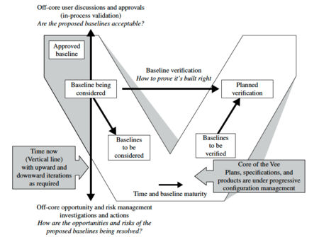
Figure 1. Left Side of the Sequential Vee Model (INCOSE 2015, adapted from Forsberg, Mooz, and Cotterman 2005, Reprinted with permission of John Wiley & Sons Inc. All other rights are reserved by the copyright owner.
The Vee Model endorses the INCOSE Systems Engineering Handbook (INCOSE 2015) definition of life cycle stages and their purposes or activities, as shown in Figure 2 below. Replace Figure 2 with the updated figure that removes the first Exploratory stage.

Figure 2. An Example of Stages, Their Purposes and Major Decision Gates. (SEBoK Original)
A more detailed version of the Vee diagram incorporates life cycle activities into the more generic Vee model. This Vee diagram, developed at the U.S. Defense Acquisition University (DAU), can be seen in Figure 3 below.
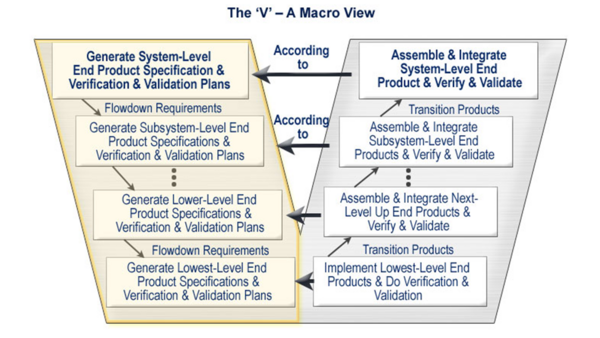
Figure 3. The Vee Activity Diagram (Prosnik 2010). Released by the Defense Acquisition University (DAU)/U.S. Department of Defense (DoD).
Application of the Vee Model
Lawson (Lawson 2010) elaborates on the activities in each life cycle stage and notes that it is useful to consider the structure of a generic life cycle stage model for any type of system-of-interest (SoI) as portrayed in Figure 4. This (T) model indicates that one or more definition stages precede a production stage(s) where the implementation (acquisition, provisioning, or development) of two or more system elements has been accomplished.
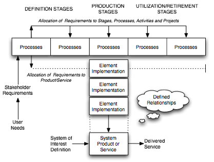
Figure 4. Generic (T) Stage Structure of System Life Cycle Models (Lawson 2010). Reprinted with permission of Harold Lawson. All other rights are reserved by the copyright owner.
Figure 5 shows the generic life cycle stages for a variety of stakeholders, from a standards organization (ISO/IEC) to commercial and government organizations. Although these stages differ in detail, they all have a similar sequential format that emphasizes the core activities as noted in Table 1 (concept, production, and utilization/retirement).
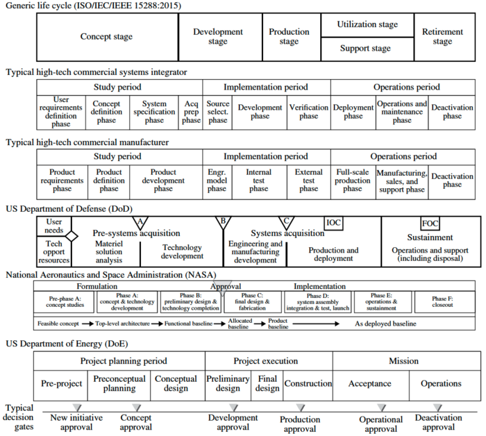
Figure 5. Comparisons of Life Cycle Models (Forsberg, Mooz, and Cotterman 2005). Reprinted with permission of John Wiley & Sons. All other rights are reserved by the copyright owner.
It is important to note that many of the activities throughout the life cycle are iterated. This is an example of recursion as discussed in the Part 3 Introduction.
Fundamentals of Life Cycle Stages and Program Management Phase
For this discussion, it is important to note that:
- The term stagestage refers to the different states of a system during its life cycle; some stages may overlap in time, such as the utilization stage and the support stage. The term “stage” is used in ISO/IEC/IEEE 15288.
- The term phase refers to the different steps of the program that support and manage the life of the system; the phases usually do not overlap. The term “phase” is used in many well-established models as an equivalent to the term “stage.”
Program managementProgram management employs phases, milestonesmilestones, and decision gatesdecision gates which are used to assess the evolution of a system through its various stages. The stages contain the activities performed to achieve goals and serve to control and manage the sequence of stages and the transitions between each stage. For each project, it is essential to define and publish the terms and related definitions used on respective projects to minimize confusion.
A typical programprogram is composed of the following phases:
- The feasibility or study phase consists of studying the feasibility of alternative concepts to reach a second decision gate before initiating the execution stage. During the feasibility phase, stakeholders' requirements and system requirements are identified, viable solutions are identified and studied, and virtual prototypes (glossary)prototypes (glossary) can be implemented. During this phase, the decision to move forward is based on:
- whether a concept is feasible and is considered able to counter an identified threat or exploit an opportunity;
- whether a concept is sufficiently mature to warrant continued development of a new product or line of products; and
- whether to approve a proposal generated in response to a request for proposal.
- The execution phase includes activities related to four stages of the system life cycle: development, production, utilization, and support. Typically, there are two decision gates and two milestones associated with execution activities. The first milestone provides the opportunity for management to review the plans for execution before giving the go-ahead. The second milestone provides the opportunity to review progress before the decision is made to initiate production. The decision gates during execution can be used to determine whether to produce the developed SoI and whether to improve it or retire it.
These program management views apply not only to the SoI, but also to its elements and structure.
Life Cycle Stages
Variations of the Vee model deal with the same general stages of a life cycle:
- New projects typically begin with an exploratory research phase which generally includes the activities of concept definition, specifically the topics of business or mission analysis and the understanding of stakeholder needs and requirements. These mature as the project goes from the exploratory stage to the concept stage to the development stage.
- The production phase includes the activities of system definition and system realization, as well as the development of the system requirements (glossary)requirements (glossary) and architecture (glossary)architecture (glossary) through verification and validation.
- The utilization phase includes the activities of system deployment and system operation.
- The support phase includes the activities of system maintenance, logistics, and product and service life management, which may include activities such as service life extension or capability updates, upgrades, and modernization.
- The retirement phase includes the activities of disposal and retirement, though in some models, activities such as service life extension or capability updates, upgrades, and modernization are grouped into the "retirement" phase.
Additional information on each of these stages can be found in the sections below (see links to additional Part 3 articles above for further detail). It is important to note that these life cycle stages, and the activities in each stage, are supported by a set of systems engineering management processes.
Concept Stage
User requirements analysis and agreement is part of the concept stage and is critical to the development of successful systems. Without proper understanding of the user needs, any system runs the risk of being built to solve the wrong problems. The first step in the concept stage is to define the user (and stakeholder) requirements and constraints. A key part of this process is to establish the feasibility of meeting the user requirements, including technology readiness assessment. As with many SE activities this is often done iteratively, and stakeholder needs and requirements are revisited as new information becomes available.
A recent study by the National Research Council (National Research Council 2008) focused on reducing the development time for US Air Force projects. The report notes that, “simply stated, systems engineering is the translation of a user’s needs into a definition of a system and its architecture through an iterative process that results in an effective system design.” The iterative involvement with stakeholders is critical to the project success.
Except for the first and last decision gates of a project, the gates are performed simultaneously. See Figure 6 below.
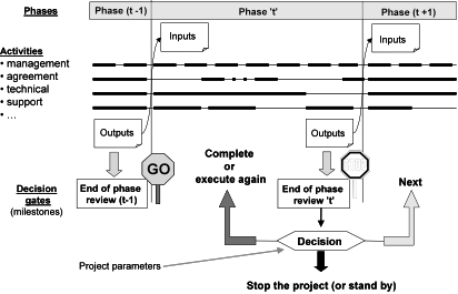
Figure 6. Scheduling the Development Phases. (SEBoK Original)
During the concept stage, alternate concepts are created to determine the best approach to meet stakeholder needs. By envisioning alternatives and creating models, including appropriate prototypes, stakeholder needs will be clarified and the driving issues highlighted. This may lead to an incremental or evolutionary approach to system development. Several different concepts may be explored in parallel.
Development Stage
The selected concept(s) identified in the concept stage are elaborated in detail down to the lowest level to produce the solution that meets the stakeholder requirementsstakeholder requirements. Throughout this stage, it is vital to continue with user involvement through in-process validation (the upward arrow on the Vee models). On hardware, this is done with frequent program reviews and a customer resident representative(s) (if appropriate). In agile development, the practice is to have the customer representative integrated into the development team.
Production Stage
The production stage is where the SoI is built or manufactured. Product modifications may be required to resolve production problems, to reduce production costs, or to enhance product or SoI capabilities. Any of these modifications may influence system requirements and may require system re-qualificationqualification, re-verificationverification, or re-validationvalidation. All such changes require SE assessment before changes are approved.
Utilization Stage
A significant aspect of product life cycle management is the provisioning of supporting systems which are vital in sustaining operation of the product. While the supplied product or service may be seen as the narrow system-of-interest (NSOI) for an acquireracquirer, the acquirer also must incorporate the supporting systems into a wider system-of-interest (WSOI). These supporting systems should be seen as system assets that, when needed, are activated in response to a situation that has emerged in respect to the operation of the NSOI. The collective name for the set of supporting systems is the integrated logistics support (ILS) system.
It is vital to have a holistic view when defining, producing, and operating system products and services. In Figure 7, the relationship between system design and development and the ILS requirements is portrayed.
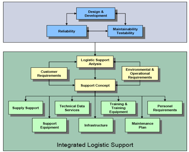
Figure 7. Relating ILS to the System Life Cycle (Eichmueller and Foreman 2009). Reprinted with permission of of ASD/AIA S3000L Steering Committee. All other rights are reserved by the copyright owner.
The requirements for reliability, resulting in the need of maintainability and testability, are driving factors.
Support Stage
In the support stage, the SoI is provided services that enable continued operation. Modifications may be proposed to resolve supportability problems, to reduce operational costs, or to extend the life of a system. These changes require SE assessment to avoid loss of system capabilities while under operation. The corresponding technical process is the maintenance process.
Retirement Stage
In the retirement stage, the SoI and its related services are removed from operation. SE activities in this stage are primarily focused on ensuring that disposal requirements are satisfied. In fact, planning for disposal is part of the system definition during the concept stage. Experiences in the 20th century repeatedly demonstrated the consequences when system retirement and disposal was not considered from the outset. Early in the 21st century, many countries have changed their laws to hold the creator of a SoI accountable for proper end-of-life disposal of the system.
Life Cycle Reviews
To control the progress of a project, different types of reviews are planned. The most commonly used are listed as follows, although the names are not universal:
- The system requirements review (SRR) is planned to verify and validate the set of system requirements before starting the detailed design activities.
- The preliminary design reviewpreliminary design review (PDR) is planned to verify and validate the set of system requirements, the design artifacts, and justification elements at the end of the first engineering loop (also known as the "design-to" gate).
- The critical design reviewcritical design review (CDR) is planned to verify and validate the set of system requirements, the design artifacts, and justification elements at the end of the last engineering loop (the “build-to” and “code-to” designs are released after this review).
- The integrationintegration, verificationverification, and validationvalidation reviews are planned as the components are assembled into higher level subsystems and elements. A sequence of reviews is held to ensure that everything integrates properly and that there is objective evidence that all requirements have been met. There should also be an in-process validation that the system, as it is evolving, will meet the stakeholders’ requirements (see Figure 7).
- The final validation review is carried out at the end of the integration phase.
- Other management related reviews can be planned and conducted in order to control the correct progress of work, based on the type of system and the associated risks.

Figure 8. Right Side of the Vee Model (Forsberg, Mooz, and Cotterman 2005). Reprinted with permission of John Wiley & Sons Inc. All other rights are reserved by the copyright owner.
References
Works Cited
Eichmueller, P. and B. Foreman. 2010. S3000LTM. Brussels, Belgium: Aerospace and Defence Industries Association of Europe (ASD)/Aerospace Industries Association (AIA).
Faisandier, A. 2012. Systems Architecture and Design. Belberaud, France: Sinergy'Com.
Forsberg, K., H. Mooz, and H. Cotterman. 2005. Visualizing Project Management, 3rd ed. New York, NY, USA: J. Wiley & Sons.
INCOSE. 2012. Systems Engineering Handbook: A Guide for System Life Cycle Processes and Activities, version 3.2.2. San Diego, CA, USA: International Council on Systems Engineering (INCOSE), INCOSE-TP-2003-002-03.2.2.
Lawson, H. 2010. A Journey Through the Systems Landscape. London, UK: College Publications, Kings College, UK.
Primary References
Beedle, M., et al. 2009. "The Agile Manifesto: Principles behind the Agile Manifesto". in The Agile Manifesto [database online]. Accessed December 04 2014 at www.agilemanifesto.org/principles.html
Boehm, B. and R. Turner. 2004. Balancing Agility and Discipline. New York, NY, USA: Addison-Wesley.
Fairley, R. 2009. Managing and Leading Software Projects. New York, NY, USA: J. Wiley & Sons.
Forsberg, K., H. Mooz, and H. Cotterman. 2005. Visualizing Project Management. 3rd ed. New York, NY, USA: J. Wiley & Sons.
INCOSE. 2012. Systems Engineering Handbook: A Guide for System Life Cycle Processes and Activities, version 3.2.2. San Diego, CA, USA: International Council on Systems Engineering (INCOSE), INCOSE-TP-2003-002-03.2.2.
Lawson, H. 2010. A Journey Through the Systems Landscape. Kings College, UK: College Publications.
Pew, R., and A. Mavor (eds.) 2007. Human-System Integration in the System Development Process: A New Look. Washington, DC, USA: The National Academies Press.
Royce, W.E. 1998. Software Project Management: A Unified Framework. New York, NY, USA: Addison Wesley.
Additional References
Anderson, D. 2010. Kanban. Sequim, WA, USA: Blue Hole Press.
Baldwin, C. and K. Clark. 2000. Design Rules: The Power of Modularity. Cambridge, MA, USA: MIT Press.
Beck, K. 1999. Extreme Programming Explained. New York, NY, USA: Addison Wesley.
Beedle, M., et al. 2009. "The Agile Manifesto: Principles behind the Agile Manifesto". in The Agile Manifesto [database online]. Accessed 2010. Available at: www.agilemanifesto.org/principles.html
Biffl, S., A. Aurum, B. Boehm, H. Erdogmus, and P. Gruenbacher (eds.). 2005. Value-Based Software Engineering. New York, NY, USA: Springer.
Boehm, B. 1988. “A Spiral Model of Software Development.” IEEE Computer 21(5): 61-72.
Boehm, B. 2006. “Some Future Trends and Implications for Systems and Software Engineering Processes.” Systems Engineering. 9(1): 1-19.
Boehm, B., A. Egyed, J. Kwan, D. Port, A. Shah, and R. Madachy. 1998. “Using the WinWin Spiral Model: A Case Study.” IEEE Computer. 31(7): 33-44.
Boehm, B., R. Turner, J. Lane, S. Koolmanojwong. 2014 (in press). Embracing the Spiral Model: Creating Successful Systems with the Incremental Commitment Spiral Model. Boston, MA, USA: Addison Wesley.
Castellano, D.R. 2004. “Top Five Quality Software Projects.” CrossTalk. 17(7) (July 2004): 4-19. Available at: http://www.crosstalkonline.org/storage/issue-archives/2004/200407/200407-0-Issue.pdf
Checkland, P. 1981. Systems Thinking, Systems Practice. New York, NY, USA: Wiley.
Crosson, S. and B. Boehm. 2009. “Adjusting Software Life cycle Anchorpoints: Lessons Learned in a System of Systems Context.” Proceedings of the Systems and Software Technology Conference, 20-23 April 2009, Salt Lake City, UT, USA.
Dingsoyr, T., T. Dyba. and N. Moe (eds.). 2010. "Agile Software Development: Current Research and Future Directions.” Chapter in B. Boehm, J. Lane, S. Koolmanjwong, and R. Turner, Architected Agile Solutions for Software-Reliant Systems. New York, NY, USA: Springer.
Dorner, D. 1996. The Logic of Failure. New York, NY, USA: Basic Books.
Forsberg, K. 1995. "'If I Could Do That, Then I Could…' System Engineering in a Research and Development Environment.” Proceedings of the Fifth Annual International Council on Systems Engineering (INCOSE) International Symposium. 22-26 July 1995. St. Louis, MO, USA.
Forsberg, K. 2010. “Projects Don’t Begin With Requirements.” Proceedings of the IEEE Systems Conference, 5-8 April 2010, San Diego, CA, USA.
Gilb, T. 2005. Competitive Engineering. Maryland Heights, MO, USA: Elsevier Butterworth Heinemann.
Goldratt, E. 1984. The Goal. Great Barrington, MA, USA: North River Press.
Hitchins, D. 2007. Systems Engineering: A 21st Century Systems Methodology. New York, NY, USA: Wiley.
Holland, J. 1998. Emergence. New York, NY, USA: Perseus Books.
ISO/IEC. 2010. Systems and Software Engineering, Part 1: Guide for Life Cycle Management. Geneva, Switzerland: International Organization for Standardization (ISO)/International Electrotechnical Commission (IEC), ISO/IEC 24748-1:2010.
ISO/IEC/IEEE. 2015. Systems and Software Engineering -- System Life Cycle Processes. Geneva, Switzerland: International Organisation for Standardisation / International Electrotechnical Commissions / Institute of Electrical and Electronics Engineers. ISO/IEC/IEEE 15288:2015.
ISO/IEC. 2003. Systems Engineering — A Guide for The Application of ISO/IEC 15288 System Life Cycle Processes. Geneva, Switzerland: International Organization for Standardization (ISO)/International Electrotechnical Commission (IEC), ISO/IEC 19760:2003 (E).
Jarzombek, J. 2003. “Top Five Quality Software Projects.” CrossTalk. 16(7) (July 2003): 4-19. Available at: http://www.crosstalkonline.org/storage/issue-archives/2003/200307/200307-0-Issue.pdf.
Kruchten, P. 1999. The Rational Unified Process. New York, NY, USA: Addison Wesley.
Landis, T. R. 2010. Lockheed Blackbird Family (A-12, YF-12, D-21/M-21 & SR-71). North Branch, MN, USA: Specialty Press.
Madachy, R. 2008. Software Process Dynamics. Hoboken, NJ, USA: Wiley.
Maranzano, J.F., S.A. Rozsypal, G.H. Zimmerman, G.W. Warnken, P.E. Wirth, D.W. Weiss. 2005. “Architecture Reviews: Practice and Experience.” IEEE Software. 22(2): 34-43.
National Research Council of the National Academies (USA). 2008. Pre-Milestone A and Early-Phase Systems Engineering. Washington, DC, USA: The National Academies Press.
Osterweil, L. 1987. “Software Processes are Software Too.” Proceedings of the SEFM 2011: 9th International Conference on Software Engineering. Monterey, CA, USA.
Poppendeick, M. and T. Poppendeick. 2003. Lean Software Development: an Agile Toolkit. New York, NY, USA: Addison Wesley.
Rechtin, E. 1991. System Architecting: Creating and Building Complex Systems. Upper Saddle River, NY, USA: Prentice-Hall.
Rechtin, E., and M. Maier. 1997. The Art of System Architecting. Boca Raton, FL, USA: CRC Press.
Schwaber, K. and M. Beedle. 2002. Agile Software Development with Scrum. Upper Saddle River, NY, USA: Prentice Hall.
Spruill, N. 2002. “Top Five Quality Software Projects.” CrossTalk. 15(1) (January 2002): 4-19. Available at: http://www.crosstalkonline.org/storage/issue-archives/2002/200201/200201-0-Issue.pdf.
Stauder, T. 2005. “Top Five Department of Defense Program Awards.” CrossTalk. 18(9) (September 2005): 4-13. Available at http://www.crosstalkonline.org/storage/issue-archives/2005/200509/200509-0-Issue.pdf.
Warfield, J. 1976. Societal Systems: Planning, Policy, and Complexity. New York, NY, USA: Wiley.
Womack, J. and D. Jones. 1996. Lean Thinking. New York, NY, USA: Simon and Schuster.
Relevant Videos
< Previous Article | Parent Article | Next Article >
SEBoK v. 2.9, released 20 November 2023


