Difference between revisions of "System Realization"
(No difference)
|
Revision as of 20:58, 9 August 2011
Introductory Paragraph(s)
Topics
The topics contained within this knowledge area include:
Introduction
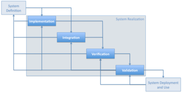
The SEBOK divides the traditional life cycle process steps into four stages. This chapter will discuss the realization stage. The processes included in realization are those required to build a system, integrate disparate system elements, and ensure that the system both meets the needs of stakeholders and aligns with the requirements identified in the system definition stages. These processes are not sequential; their iteration and flow are depicted in Figure 1, which also shows how these processes fit within the context of the System Definition and System Deployment and Use knowledge areas.
Figure 1 System Realization (Developed for BKCASE)
Essentially, the outputs of system definition are used during implementation to create system elements and during integration to provide plans and criteria for combining these elements. The requirements derived as part of System Definition are used to verify and validate System Elements, systems, and the overall system of interest (soi) . These activities provide feedback into the system design, particularly when problems or challenges are identified. Finally, when the system is considered verified and validated, it will then become an input to system deployment and use. It is important to understand that there is overlap in these activities; they do not have to occur in sequence. The way these activities are performed is dependent upon the life cycle model in use (for additional information on life cycles, see the Systems Engineering Life Cycles Knowledge Area (KA).
The realization processes are designed to ensure that the system will be ready to transition and have the appropriate structure and behavior to enable desired operation and functionality throughout the system’s life span. Both DAU and NASA include “transition” in realization in addition to implementation, integration, verification, and validation. (Prosnik 2010; NASA December 2007, 1-360) However, the SEBoK includes transition in the System Deployment and Use KA.
Fundamentals
Macro view of realization processes
Figure 2 illustrates a macro view of generic outputs from realization activities when using a Vee life cycle model. The left side of the Vee represents various design activities 'going down' the system. File:The V - A Macro View.png
Figure 2 - The Vee Activity Diagram (Prosnik. 2010)
The left side of the Vee model demonstrates the development of System Elements specifications and design descriptions. In this stage, verification and validation plans are developed which are later used to determine whether realized System Elements (Products, Services, or Enterprises) are compliant with specifications and stakeholder requirements . Also during this stage, initial specifications become flow-down requirements for lower-level system models. In terms of time frame, these activities are going on ‘early’ in the system’s life cycle. These activities are discussed in the System Definition Knowledge Area. However, it is important to understand that some of the System Realization activities are initiated at the same time as some System Definition activities.
The right side of the Vee model, as illustrated in Figure 2, results in System Elements that are assembled into Products, Services, or Enterprises according to the system model described during the left side of the Vee. Verification and validation activities determine how well the realized system fulfills the stakeholder requirements , the system requirements and design properties . These activities should follow the plans developed on the left side of the Vee.
For example, the U.S. Defense Acquisition University (DAU) provides this overview of what occurs during system realization:
"Once the products of all system models have been fully defined, Bottom-Up End Product Realization can be initiated. This begins by applying the Implementation Process to buy, build, code or reuse end products. These implemented end products are verified against their design descriptions and specifications, validated against Stakeholder Requirements and then transitioned to the next higher system model for integration. End products from the Integration Process are successively integrated upward, verified and validated, transitioned to the next acquisition phase or transitioned ultimately as the End Product to the user." (Prosnik. 2010)
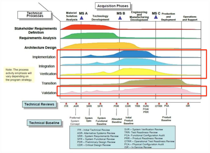
While the systems engineering technical processes are life cycle processes, the processes are concurrent, and the emphasis of the respective processes depends on the phase and maturity of the design. Figure 3 portrays (from left to right) a notional emphasis of the respective processes throughout the systems acquisition life cycle from the perspective of the U.S. Department of Defense (DoD). It is important to note that, from this perspective, these processes do not follow a linear progression. Instead, they are concurrent, with the amount of activity in a given area changing over the system’s life cycle. The red boxes indicate the topics that will be discussed below as part of realization.
Figure 3 - Notional Emphasis of Systems Engineering Technical processes and Program Life-Cycle Phases (DAU February 19, 2010)/Released)
Ontology for System Realization
For general explanations about ontology, refers to the section "Ontology for System Development" in the System Definition Introduction. The figure 4 below presents an overview of ontology elements used within System Realization activities. A set of major entities, attributes, and relationships are suggested and defined in the following sections; they are consistent with System Definition ontology elements.
Figure 4 - A simplified view of a meta-data model for System Realization. (Faisandier, 2011)
References
Please make sure all references are listed alphabetically and are formatted according to the Chicago Manual of Style (15th ed). See the BKCASE Reference Guidance for additional information.
Citations
List all references cited in the article. Note: SEBoK 0.5 uses Chicago Manual of Style (15th ed). See the BKCASE Reference Guidance for additional information.
DAU. February 19, 2010. Defense acquisition guidebook (DAG). Ft. Belvoir, VA, USA: Defense Acquisition University (DAU)/U.S. Department of Defense.
Prosnik, G. 2010. Materials from "systems 101: Fundamentals of systems engineering planning, research, development, and engineering". DAU distance learning program. eds. J. Snoderly, B. Zimmerman. Ft. Belvoir, VA, USA: Defense Acquisition University (DAU)/U.S. Department of Defense (DoD).
Primary References
All primary references should be listed in alphabetical order. Remember to identify primary references by creating an internal link using the ‘’’reference title only’’’ (title). Please do not include version numbers in the links.
INCOSE . 2011. INCOSE Systems Engineering Handbook, Version 3.2.1 (Jan 2011) San Diego, CA, USA: International Council on Systems Engineering (INCOSE).
ISO/IEC. 2008. Systems and software engineering - system life cycle processes. Geneva, Switzerland: International Organization for Standardization (ISO)/International Electronical Commission (IEC), ISO/IEC 15288:2008 (E).
Martin, J. N. 1997. Systems engineering guidebook: A process for developing systems and products. 1st ed. Boca Raton, FL, USA: CRC Press.
NASA. December 2007. Systems engineering handbook. Washington, D.C.: National Aeronautics and Space Administration (NASA), NASA/SP-2007-6105.
Additional References
All additional references should be listed in alphabetical order.
DAU. February 19, 2010. Defense acquisition guidebook (DAG). Ft. Belvoir, VA, USA: Defense Acquisition University (DAU)/U.S. Department of Defense.
DAU. Your acquisition policy and discretionary best practices guide. In Defense Acquisition University (DAU)/U.S. Department of Defense (DoD) [database online]. Ft Belvoir, VA, USA, 2009 Available from https://dag.dau.mil/Pages/Default.aspx (accessed 2010).
ECSS. 6 March 2009. Systems engineering general requirements. Noordwijk, Netherlands: Requirements and Standards Division, European Cooperation for Space Standardization (ECSS), ECSS-E-ST-10C.

