Difference between revisions of "Systems Engineering and Management"
| Line 90: | Line 90: | ||
===Citations=== | ===Citations=== | ||
List all references cited in the article. Note: SEBoK 0.5 uses Chicago Manual of Style (15th ed). See the [http://www.bkcase.org/fileadmin/bkcase/files/Wiki_Files__for_linking_/BKCASE_Reference_Guidance.pdf BKCASE Reference Guidance] for additional information. | List all references cited in the article. Note: SEBoK 0.5 uses Chicago Manual of Style (15th ed). See the [http://www.bkcase.org/fileadmin/bkcase/files/Wiki_Files__for_linking_/BKCASE_Reference_Guidance.pdf BKCASE Reference Guidance] for additional information. | ||
| + | |||
| + | Oliver, D., T. Kelliher, and J. Keegan. 1997. Engineering complex systems with models and objects. New York, NY: McGraw-Hill. | ||
| + | |||
| + | |||
| + | ISO. 2007. Systems engineering and design. Geneva, Switzerland: International Organization for Standardization (ISO), ISO 10303-AP233. | ||
===Primary References=== | ===Primary References=== | ||
Revision as of 03:36, 30 August 2011
This part of the SEBOK concentrates upon the generic knowledge of HOW to engineer systems. It provides a basis for the engineering of product systems , the engineering of service systems , the engineering of an enterprise system as well as the engineering of systems of systems as described in Part 4.
Managing System Assets
Organizations and their enterprises must continually monitor their portfolio of system assets; that is, their value added product system and/or service system offerings as well as all of the systems that support their development or operations (often referred to as infrastructure systems). Proper management of their system assets as illustrated in the System Coupling Diagram is essential for achieving enterprise purpose, goals and missions in responding to situations.
Key to operations of an enterprise, are the decisions that are made concerning system assets. Thus, prudent change management based upon enterprise needs and the problem and opportunity situations that it encounters must be a central function of enterprise leadership and management at all levels (strategic, tactical, and operational). Changes can involve the creation of new systems, the modification of existing systems or the deletion (retiring) of systems; as well as the altering of operational parameters for systems that are in operation.
The knowledge areas of this part provide generic insight into various aspects of how to accomplish life cycle relevant changes in respect to the types of engineered systems described in Part 4.
Generic Systems Engineering Paradigm
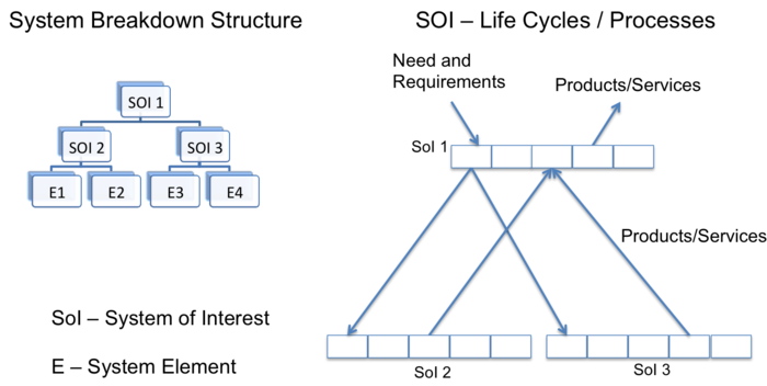
In order to establish a basis for the Knowledge Areas of Part 3 and Part 4, the paradigm appearing in Figure 1 identifies the general goal of any Systems Engineering effort. That is the understanding of stakeholder value, the selection of a specific need; the transformation of that need into a system product or service that provides for the need; and the use of that product or service to provide the stakeholder value. This paradigm has been developed according to the principles of a systems approach described in the Applying the Systems Approach topic in Part 2.
Figure 1. Generic Systems Engineering Paradigm (Lawson, 2011)
On the left hand side of the figure observe that there are three Systems of Interest identified in the form of a system breakdown structure . SOI 1 is decomposed into its elements which in this case are systems as well (SOI 2 and SOI 3). These two systems are composed of system elements which are not further refined.
On the right hand side of the figure observe that each of the Systems of Interest has a corresponding life cycle model composed of stages that are populated with processes that are used to define the work to be performed. Note that some of the requirements defined to meet the need are distributed in the early stages of the life cycle for SOI 1 to the life cycles of SOI 2, respectively SOI 3. This decomposition of the system illustrates the fundamental concept of recursion as defined in the ISO/IEC 15288 standard. That is the standard is reapplied for each of the systems of interest.
Note that the system elements are integrated in SOI 2, respectively SOI 3 thus realizing a product or service that is delivered to the life cycle of SOI 1 for integration in realizing the product or service that meets the stated need.
Some examples that relate to this system need could be an embedded system (SOI 1) composed a hardware system (SOI 2) and a software system (SOI 3), a sub-assembly composed of a chasis and a motor, a human resource system composed of a recruitment system and a capability management system.
In performing the process work in stages, most often iteration between stages if required. For example, in successive refinement of the definition of the system or in providing an update (upgrade or problem solution) of a realized and even delivered product or service.
The work performed in the processes and stages can be performed in a concurrent manner within the life cycle of any of the systems of interest and concurrent amongst the multiple life cycles.
This paradigm provides a fundamental framework for understanding generic systems engineering in Part 3 as well as for the application of systems engineering in the provisioning of the various types of systems described in Part 4.
Applying Iteration and Recursion to Systems Engineering in the Life Cycle
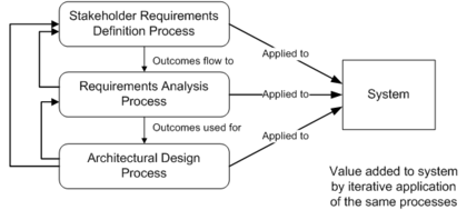
The concept of iteration is applied also for processes. Figure 2 below gives an example of iteration of three processes as defined in ISO-IEC 15288. The processes in this example are further discussed in the System Definition knowledge area.
Figure 2. Example of iterations of processes related to System Definition (ISO. 2003)
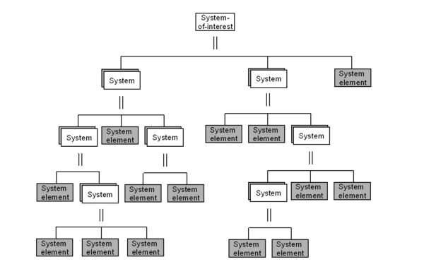
The complete definition of a System of Interest (SoI) is generally achieved considering decomposition layers of systems and of System Elements. Figure 3 presents a fundamental schema of a system breakdown structure.
Figure 3. Hierarchical decomposition of a system-of-interest (ISO/IEC. 2008)
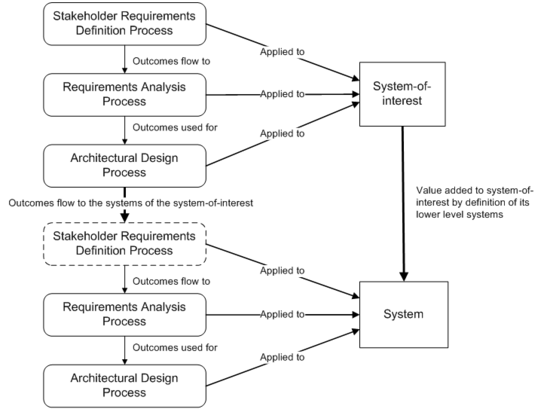
In each decomposition layer and for each system, the System Definition processes are applied recursively because the notion of system is recursive; the notions of System-of-Interest (SOI), system, system element are based on the same concepts – see Part 2. Figure 4 shows an example of recursion of three processes as defined in ISO/IEC 15288.
Figure 4. Recursion of processes on layers (ISO. 2003)
Value of Ontology Concepts for Systems Engineering
Ontology is the set of entities presupposed by a theory (Collins English Dictionary). SE, and in particular system development, can be considered a theory because it is based on concepts related to mathematics and proven practices. A SE ontology can be defined considering the following path.
SE provides engineers with an approach based on a set of concepts (i.e. Stakeholder, Requirement, Function, Scenario, System Element, etc.) and generic processes. Each process is composed of a set of activities and tasks gathered logically around a theme or a purpose. A process describes “what to do” using the concepts. The implementation of the activities and tasks is supported by methods and modeling techniques, composed themselves of elementary tasks; they describe the “how to do”. The activities and tasks of SE are transformations of generic data using the predefined concepts. Those generic data are called Entities, Classes, or Types. Each entity is characterized by specific attributes, and each attribute can get different values. All along their execution, the activities and tasks of processes, methods, and modeling techniques exchange instances of generic entities according to logical relationships. These relationships allow the engineer to link the entities between themselves (traceability) and to follow a logical sequence of the activities and the global progression (engineering management). Cardinality is associated with every relationship, expressing the minimum and maximum number of entities in order to make the relationship valid. Additional information may be found in (Oliver, Kelliher, and Keegan. 1997).
The set of SE entities and their relationships form an ontology also often called Engineering Meta-model. Such an approach is used and defined in the standard (ISO 2007). The benefits of using an ontology are many. The ontology allows or forces:
- the use of a standardized vocabulary, using the right names and avoiding using synonyms in the processes, methods, and modeling techniques;
- reconciliation of the vocabulary used in different modeling techniques and methods;
- the automatic appearance of traceability of requirements when implemented in databases, SE tools or workbenches, and also the quick identification of the impacts of modifications in the engineering data set;
- checks of the consistency and completeness of engineering data, etc.
Mapping of Topics to ISO/IEC 15288, System Life Cycle Processes
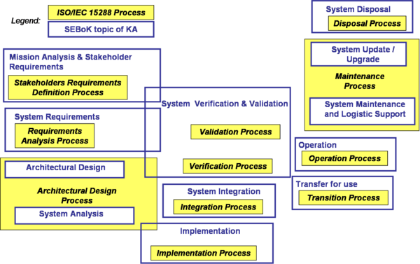
Note: To facilitate readers' understanding of the standard ISO/IEC. 2008, the Figure below shows the relative position of the Technical Knowledge Areas (KA) of this SEBoK with respect to the processes as stated in the standard.
Figure 4. Mapping of technical topics of Knowledge Areas of SEBoK with ISO/IEC 15288 Technical Processes
Knowledge Areas in Part 3
- Life Cycle Models
- System Definition
- System Realization
- System Deployment and Use
- Systems Engineering Management
- Product and Service Life Management
- Systems Engineering Standards
References
Please make sure all references are listed alphabetically and are formatted according to the Chicago Manual of Style (15th ed). See the BKCASE Reference Guidance for additional information.
Citations
List all references cited in the article. Note: SEBoK 0.5 uses Chicago Manual of Style (15th ed). See the BKCASE Reference Guidance for additional information.
Oliver, D., T. Kelliher, and J. Keegan. 1997. Engineering complex systems with models and objects. New York, NY: McGraw-Hill.
ISO. 2007. Systems engineering and design. Geneva, Switzerland: International Organization for Standardization (ISO), ISO 10303-AP233.
Primary References
All primary references should be listed in alphabetical order. Remember to identify primary references by creating an internal link using the ‘’’reference title only’’’ (title). Please do not include version numbers in the links.
Additional References
All additional references should be listed in alphabetical order.
