Difference between revisions of "Logical Architecture"
Wikiexpert (talk | contribs) m (Text replace - "==Citations==" to "==Works Cited==") |
Wikiexpert (talk | contribs) |
||
| Line 174: | Line 174: | ||
{{DISQUS}} | {{DISQUS}} | ||
| + | [[Category:System Definition]] | ||
Revision as of 11:46, 23 February 2012
Architectural design explores, defines, and formalizes solutions that meet the system requirements and selects the optimal solution while taking system requirements into account.
Definition and Purpose of Architectural Design
The architectural design of a system creates a solution based on principles and concepts logically related and consistent to each other that possess properties and characteristics that satisfy a problem. It is implementable within a predefined set of system requirements.
The properties and characteristics are classified and modeled while activities are designed that take into account views such as functional, temporal, behavioral, performance, operational, environmental, and structural. See the Fundamentals of System Definition section for more information. A design-properties-oriented classification (see System Requirements) facilitates these views.
Considerations include:
- Functional, behavioral, and temporal views – The functional description (independent from the implementation technologies) is essential. A temporal and decision monitoring model supplements the functional and behavioral models to organize the in-service management of the system in order to achieve its mission and purpose permanently.
- Performance, operational, environmental, and structural views – The projection or allocation of functional, behavioral, and temporal models onto a physical architecture (dependent on the implementation technologies) includes the definition of systems, system elements , and physical connections (physical interfaces ) that together own design properties , such as:
- structural properties (simplicity, modularity, adaptability, scalability, reusability, portability, commonality, expandability, etc.);
- effectiveness/performance levels, accuracy, etc.;
- operational characteristics (usability, availability, maintainability, reliability, testability, robustness, interoperability, integrity, generality, training, etc.); and
- environmental characteristics (heatproof, shockproof, electrical resistance, radiation resistance, etc.).
- Confidence in the solution – The confidence obtained by correctly designing the architecture and finding the optimal solution given the complete set of system requirements is an essential aspect related to the assessment of the properties and characteristics of the system that are performed during design (refer to System Analysis topic for more information).
Various architectural models should cover the properties listed above; multiple models can be used to represent all properties. An issue in today's society concerns the consistency between all models attempting to represent the global solution.
Principles Governing Architectural Design
Architectural design relies on known concepts and/or patterns such as interface, function, input-output-control flow, dynamics, temporal and decision hierarchy, allocation and partitioning, emerging properties, etc.
The principles are well described in The Engineering Design of Systems: Models and Methods (Buede, 2009) and The Art of Systems Architecting (Maier and Rechtin, 2009).
Process Approach – Architectural Design
As a minimum, the architectural solution consists of both a functional/logical architecture (expressed as a set of functions, scenarios, and/or operational models) and a physical architecture (expressed as a set of systems with system elements physically connected between them) associated to a set of design properties.
Transition from System Requirements to Physical Architecture
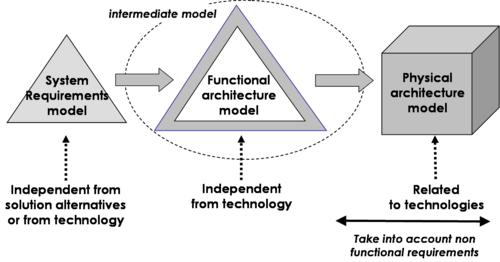
As Figure 1 illustrates, design progresses from a system requirements baseline (representing the problem from a supplier/designer point of view while remaining as independent of technology as possible) to an intermediate model of functional architecture (dependent on design decisions) and then allocates the elements of the functional architecture to the elements of potential physical architectures. The technological solutions are selected according to performance criteria and non-functional requirements, such as the operational conditions and life cycle constraints (e.g., environmental conditions, maintenance constraints, realization constraints, etc.).
Iterations Between Functional and Physical Architectures Design
Design activities require iterations looping from functional to physical design and vice versa until both the functional and physical architectures are exhaustive and consistent.
The first design loop creates a functional design based on the nominal scenarios. The goal is to actualize the first model that could potentially achieve the mission of the system. The physical design then enables the engineer to determine the main system elements that will perform these functions and to organize them into a physical architecture.
A second functional design loop considers the allocations of functions onto system elements and the derived functions coming from physical solution choices. This loop also supplements the initial functional model by introducing other altered models, failed analyses, and every operational requirement not performed in the first loop. The derived functions must, in their turn, be allocated to system elements and this, in turn, affects the physical design.
Eventually, other design loops produce an exhaustive and consistent functional and physical solution. During design, technological choices potentially lead to new functions, new input/output and control flows, and new physical interfaces. These new elements conduct the creation of new system requirements called “derived requirements” that become part of the requirements baseline.
Generic Inputs and Outputs of the Design Process
The inputs and outputs of the design process evolve incrementally because of the necessity of iterative execution in the process. The generic inputs include the system requirements, initial generic design patterns, outcome from the System Analysis, and feedback from the System Verification and System Validation.
The generic outputs are the selected functional and physical architectures of the system of interest (SOI), the stakeholder requirements of every system element that comprises the physical architecture of the system of interest, the interface requirements between the system elements, and the elements from rejected solutions.
Activities of the Process
Major activities and tasks performed during this process include:
- Define the functional architecture of the system, that is:
- Identify functions, input/output flows, operational modes, transition of modes, and operational scenarios from the system requirements by analyzing the functional, interface, and operational requirements.
- Define the necessary inputs and controls (energy, material, and data flows) to each function and the outputs generated thereby; deduce the necessary functions which use, transform, move, and generate the input/output flows.
- Allocate performance, effectiveness, and constraints requirements to functions and to input, output, and control flows.
- Design candidate functional architectures using the previously defined elements to model scenarios of functions and/or model sequences of operational modes and transition of modes. Integrate the scenarios of functions in order to get a complete picture of the dynamic behavior of the system and allocate the temporal constraints. Decompose the functional elements as necessary to look towards implementation. Perform functional failure modes and effects analysis and update the functional architecture as necessary.
- Select the functional architecture by assessing the candidate functional architectures against assessment criterion , as related to design properties and to requirements, and compare them. Use a system analysis process to perform the assessments (see System Analysis topic).
- Synthesize the selected functional architecture and verify its dynamic behavior. Identify the derived functional elements created for the necessity of design.
- Establish traceability between system requirements and functional architecture elements.
- Define the physical architecture of the system, that is:
- Search for system elements able to perform the functions as well as physical interfaces to carry the input, output, and control flows; ensure the system elements exist or must be engineered. Use partitioning method to perform this allocation (when it is impossible to identify a system element that performs a function, decompose the function until it is possible).
- Design potential physical architectures using the previously-defined elements to model networks of system elements and physical interfaces. For each potential candidate, this requires the working out of a low-level, physical architecture with the elementary system elements. Because these are generally too numerous (ten or more) they have to be grouped into higher-level system elements, also called systems. It is then possible to work out a high-level physical architecture with these systems and system elements.
- Select the most suitable physical architecture by assessing the candidate physical architectures against assessment criteria (related to non-functional requirements) and compare them. Use the system analysis process to perform the assessments (see the System Analysis topic).
- Synthesize the selected physical architecture; verify that it satisfies the system requirements and is realistic. Identify the derived physical elements and functional elements created for the necessity of design. Establish traceability between system requirements and physical architecture elements and allocation matrices between functional and physical elements.
- Feedback the architectural design and the system requirements, that is:
- Model the “allocated functional architecture” onto systems and system elements if such a representation is possible.
- Define the derived functional and physical elements induced by the selected functional and physical architectures. Define the corresponding derived requirements and allocate them on the appropriate functional and physical architectures elements. Incorporate these derived requirements in the requirements baselines of the systems impacted.
- Prepare the technical elements for the acquisition of each system or system element, that is:
- Define the mission and objectives of the system or system element from the functions allocated to the system or system element and the allocation of performance and effectiveness to the system or system element respectively.
- Define the stakeholder requirements for this system or system element (the concerned stakeholder being the system of interest). (Additional discussion on the development of the stakeholder requirements can be found in the Mission Analysis and Stakeholder Needs and Requirements topics.)
- Establish traceability between the stakeholder requirements of the system or system element and the design elements of the system of interest. This allows the traceability of requirements between two layers of systems.
Checking and Correctness of Architectural Design
The main items to be checked during design concern functional and physical architectures.
Concerning functional design, check that:
- Every functional and interface requirement corresponds to one or several functions.
- The outputs of functions correspond to submitted inputs.
- Every function produces at least one output.
- Functions are triggered by control flows as needed.
- Functions are sequenced in the right order and synchronized.
- The execution duration of the functions is in the range of the effectiveness or performance requirements.
- All requested operational scenarios are taken into account.
- The simulation of the functional architecture is complete in every possible case and shows that the consummation of input flows and the production of output flows are correctly sized (when simulation of models is possible).
Concerning physical design, check that:
- Every system element performs one or several functions of the functional architecture.
- Every function has been allocated to one system element.
- Every input/output flow is carried by a physical interface.
- The components of the context of the system of interest are linked to system elements with physical interfaces.
- The functional architecture is correctly projected onto the physical architecture and the allocated functional architecture reflects this projection correctly.
- The physical architecture is implementable by mastered industrial technologies.
Methods and Modeling Techniques
Design uses modeling techniques that are grouped under various types of models. Several methods have been developed to support the following types of models:
- Functional models, such as the structured analysis design technique, system analysis and real time, enhanced functional flow block diagrams (eFFBD), function analysis system technique, etc.
- Semantic models, such as entities-relationships diagram, class diagram, data flow diagram, etc.
- Dynamic models, such as state-transition diagrams, state-charts, eFFBDs, state machine diagrams, activity diagrams (OMG 2010), Petri nets, etc.
- Physical models, such as physical block diagrams, SysML blocks (OMG 2010), etc.
Practical Considerations about Architectural Design
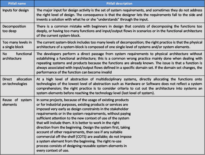
Major pitfalls encountered with architectural design are presented in Table 1.
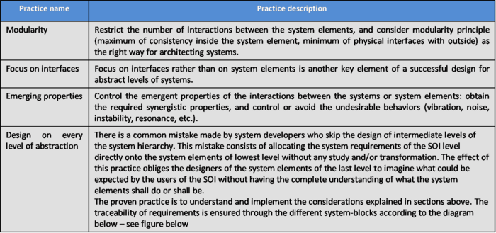
Proven practices with architectural design of systems are presented in Table 2.
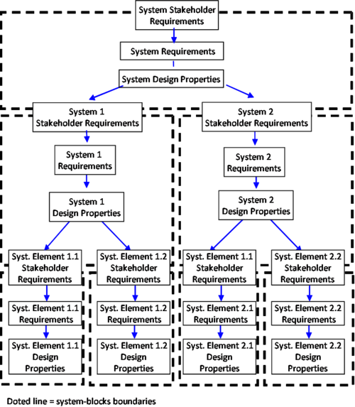
Note: Figure 2: Traceability graph referenced in Table 2, Proven Practices, above.
References
Works Cited
Alexander, C., S. Ishikawa, M. Silverstein, M. Jacobson, I. Fiksdahl-King, and S. Angel. 1977. A Pattern Language: Towns, Buildings, Construction. New York, NY, USA: Oxford University Press.
Buede, D.M. 2009. The engineering design of systems: Models and methods. 2nd ed. Hoboken, NJ, USA: John Wiley & Sons Inc.
Gamma, E., R. Helm, R. Johnson, and J. Vlissides. 1995. Design Patterns: Elements of Reusable Object-Oriented Software. Boston, MA, USA: Addison-Wesley.
Maier, M., and E. Rechtin. 2009. The art of systems architecting. 3rd ed. Boca Raton, FL, USA: CRC Press.
Oliver, D., T. Kelliher, and J. Keegan. 1997. Engineering complex systems with models and objects. New York, NY, USA: McGraw-Hill.
OMG. 2010. OMG Systems Modeling Language specification, version 1.2, July 2010. http://www.omg.org/technology/documents/spec_catalog.htm.
Thome, B. 1993. Systems Engineering, Principles & Practice of Computer-Based Systems Engineering. New York, NY, USA: Wiley.
ISO/IEC/IEEE. 2008. Systems and Software Engineering - System Life Cycle Processes. Geneva, Switzerland: International Organization for Standardization (ISO)/International Electronical Commission (IEC), Institute of Electrical and Electronics Engineers. ISO/IEC/IEEE 15288:2008 (E).
Primary References
ANSI/IEEE. 2000. Recommended practice for architectural description for software-intensive systems. New York, NY: American National Standards Institute (ANSI)/Institute of Electrical and Electronics Engineers (IEEE), ANSI/IEEE 1471-2000.
INCOSE. 2011. INCOSE Systems Engineering Handbook: A Guide for System Life Cycle Processes and Activities, version 3.2.1. San Diego, CA, USA: International Council on Systems Engineering (INCOSE), INCOSE-TP-2003-002-03.2.1.
ISO/IEC/IEEE. 2008. Systems and Software Engineering - System Life Cycle Processes. Geneva, Switzerland: International Organization for Standardization (ISO)/International Electronical Commission (IEC), Institute of Electrical and Electronics Engineers. ISO/IEC/IEEE 15288:2008 (E).
ISO/IEC/IEEE. 2011. Systems and Software Engineering - Architecture Description. Geneva, Switzerland: International Organization for Standardization (ISO)/International Electrotechnical Commission (IEC)/Institute of Electrical and Electronics Engineers (IEEE), ISO/IEC/IEEE 42010.
Maier, M., and E. Rechtin. 2009. The Art of Systems Architecting. 3rd ed. Boca Raton, FL, USA: CRC Press.
Additional References
Faisandier, A. 2011 (unpublished). Engineering and Architecting Multidisciplinary Systems.
Oliver, D., T. Kelliher, and J. Keegan. 1997. Engineering Complex Systems with Models and Objects. New York, NY, USA: McGraw-Hill.
Thome, B. 1993. Systems Engineering, Principles & Practice of Computer-Based Systems Engineering. New York, NY, USA: Wiley.
Comments from 0.5 Wiki
<html> <iframe src="http://bkcasewiki.org/index.php?title=Talk:Architectural_Design&printable=yes" width=825 height=200 frameborder=1 scrolling=auto> </iframe> </html>
SEBoK Discussion
Please provide your comments and feedback on the SEBoK below. You will need to log in to DISQUS using an existing account (e.g. Yahoo, Google, Facebook, Twitter, etc.) or create a DISQUS account. Simply type your comment in the text field below and DISQUS will guide you through the login or registration steps. Feedback will be archived and used for future updates to the SEBoK. If you provided a comment that is no longer listed, that comment has been adjudicated. You can view adjudication for comments submitted prior to SEBoK v. 1.0 at SEBoK Review and Adjudication. Later comments are addressed and changes are summarized in the Letter from the Editor and Acknowledgements and Release History.
If you would like to provide edits on this article, recommend new content, or make comments on the SEBoK as a whole, please see the SEBoK Sandbox.
blog comments powered by Disqus


